11-25
HRN216 HANDLEBAR/ CABLES/CONTROLS
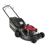
5. While holding the push knob in the Roto-Stop right case,
carefully install the right case on the left case.
• Confirm that the case halves seat together and install
the four self-tapping screws.
• Verify that the yellow push knob pushes in and
releases properly.
6. Install the Roto-Stop control on the handlebar.
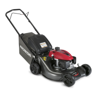
7. Route the Roto-Stop cable down through the cutter
housing and to the ball plate.
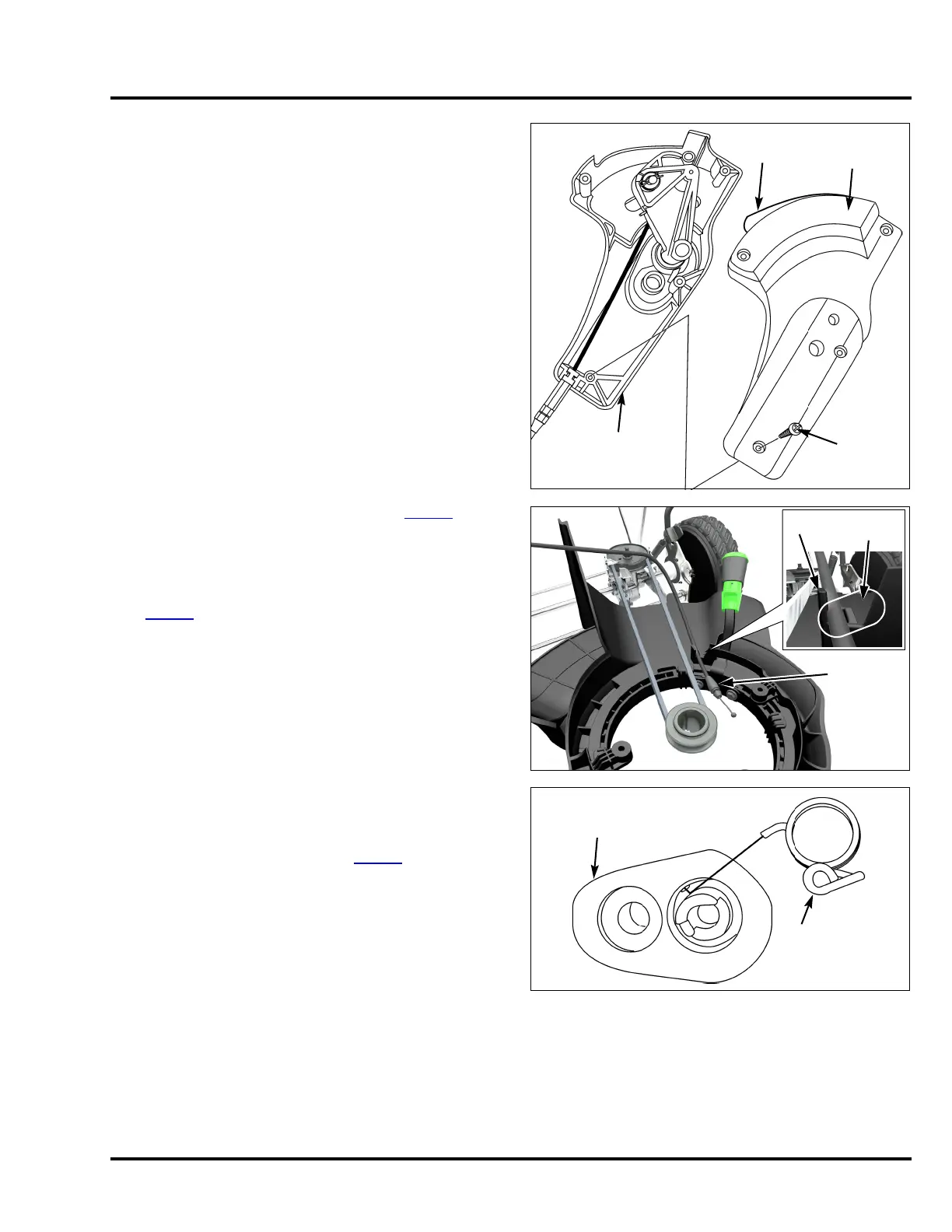
8. Install the Roto-Stop cable ball end in the ball plate.
Secure the Roto-Stop cable locking tabs in the return
spring hook.
9. Install the Roto-Stop cover and shutter (P. 1 2 -3
). Make
sure to route the Roto-Stop cable on the correct side of
the rib as shown so it does not contact the drive belt.
10. Install two new cable ties and wire holder securing the
Roto-Stop cable to the handlebar and handle stay
(P. 2-24
).
11. Install the blade control lever spring on the
Roto-Stop control assembly and install the blade control
lever.
12. Readjust the Roto-Stop cable (P. 3-13
).
13. Start the engine and confirm proper Roto-Stop
operation.
ROTO-STOP
RIGHT CASE
SELF-TAPPING
SCREW (4)
ROTO-STOP
LEFT CASE
PUSH
KNOB
RIB
Do not install
belt in this
area.
ROTO-STOP
CABLE
BLADE CONTROL
LEVER SPRING
ROTO-STOP
CONTROL
ASSEMBLY
 Loading...