3-14
MAINTENANCE HRN216
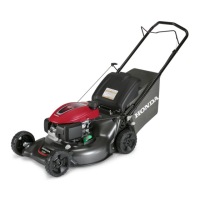
CLUTCH WEAR
With the blade control lever pushed forward against the
handlebar, use a clean feeler gauge to measure the distance
between the brake plate and the driven disk.
Replace the driven disk if below the service limit.
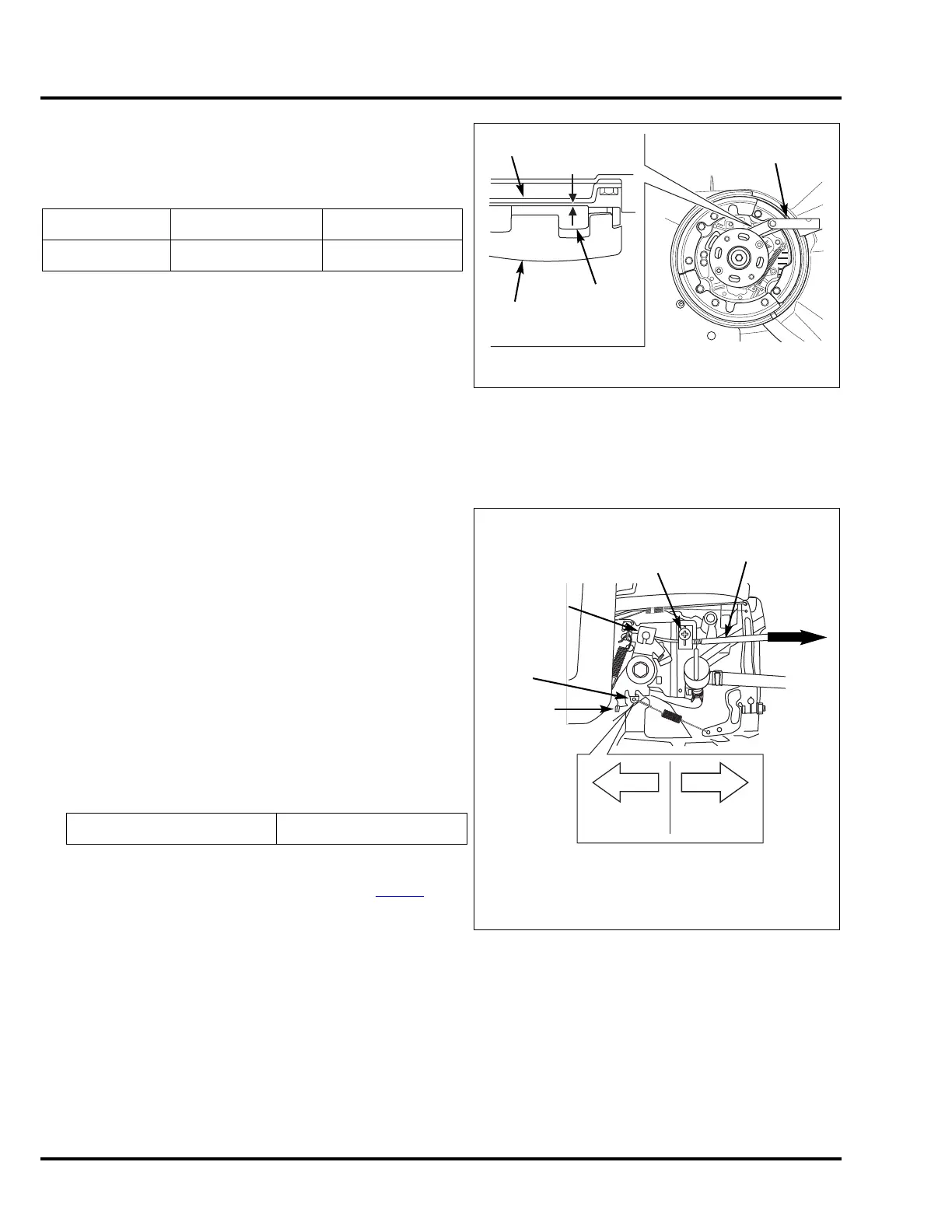
17. THROTTLE CABLE AND LINKAGE
VYA TYPE ONLY
1. Move the throttle to the FAST position.
2. With engine off, loosen the locking clamp screw holding
the cable.
3. At the control plate, pull the cable backward slowly moving
lever A and B.
4. When lever A stops moving, hold the cable in that position.
DO NOT PULL FURTHER.
Lever B can still move if you continue pulling hard enough.
5. Tighten the locking clamp screw.
6. Start the engine and let it warm up,
7. Engage the Roto-Stop
®
, and then check the engine speed
with the throttle set to the FAST position.
8. If the engine speed is not within specification, bend the
governor spring arm very slightly as needed (P. 3 - 21
):
• Left increases spring tension and engine speed.
• Right decreases spring tension and engine speed.
Standard Service limit
Clutch 2.0 mm (0.08 in) 0.5 mm (0.02 in)
Maximum governed speed 3,100 +0/-150 rpm
BLADE
HOLDER
FEELER
GAUGE
CLUTCH
WEAR
BRAKE
PLATE
DRIVEN
DISK
Blades have been removed in this illustration for clarity.
CONTROL
LEVER A
CONTROL
LEVER B
BEND
BEND
GOVERNOR
SPRING
ARM
INCREASE
SPEED
DECREASE
SPEED
PULL
LOCKING
CLAMP
SCREW
THROTTLE
CABLE
 Loading...