Extinguishing Control Computer 8010 - Series 2
104 FB 798352 / 11.07
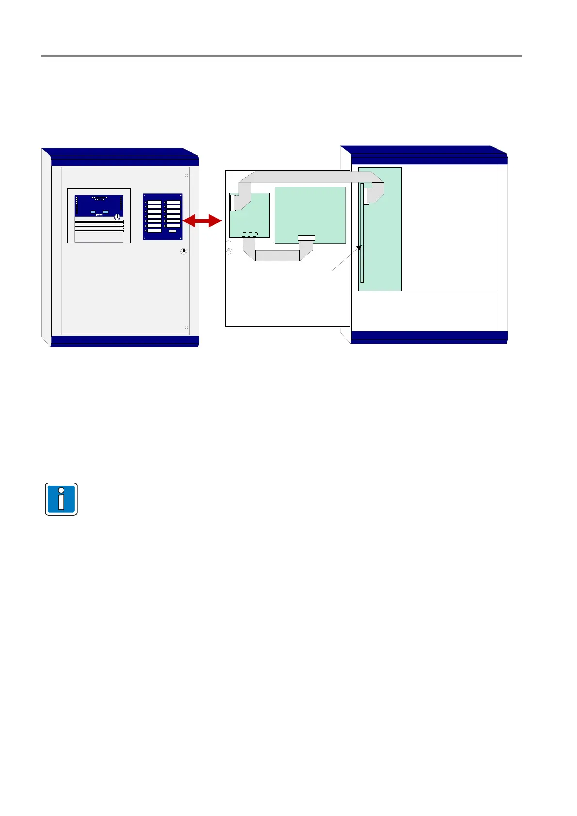
17.5 Control indicator and Alarm counter (Part No. 788016)
This optional device must be mounted on the front door of the panel housing and connected to the processor
board and the control/display panel via the ribbon cable. This device is automatically supported from system
software Version V2.01R001e and the zone board (Part No. 771793). Any additional settings are not necessary.
Control
zone
indicator
Alarmzähler
Relais (AE) 1
2
0 0 0 5
3
4
5
6
7
8
9
10
11
12
13
zone
board
processor board
(upright)
control and
display panel
Fig. 35: Control indicator and Alarm counter
The LED indicators lit when the desired output is activated. Each of the 13-relay-output has an assigned LED
indicator. The description of each output can be entered in the lettering area.
The mechanical alarm counter shows the overall number of detected fire alarms and will be automatically
incremented with each new fire alarm.
The >control indication< device must always be installed with the control and display panel.
Connect ribbon cable as shown in figure. The wrong cable connection causes a malfunction of the
panel.
 Loading...