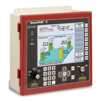
Extinguishing Control Computer 8010 - Series 2
FB 798352 / 11.07 61
11 General .....................................................................................................................................................................62
12 Display and control panel ........................................................................................................................................63
12.1 Single Zone display.......................................................................................................................................64
12.1.1 Status display of the zones.................................................................................................. 64
12.1.2 Status display of the outputs................................................................................................ 65
12.2 Operating displays.........................................................................................................................................66
12.3 Trouble displays ............................................................................................................................................68
12.4 Keypad functions...........................................................................................................................................70
12.5 Connect / disconnect zones .........................................................................................................................71
12.6 Connect / disconnect relay outputs..............................................................................................................72
12.7 Test mode......................................................................................................................................................73
12.8 Revision mode...............................................................................................................................................74
12.9 Resetting the panel 8010..............................................................................................................................75
12.10 Lamp test .......................................................................................................................................................75
13 Control indicator and Alarm counter (Option).........................................................................................................76
14 Installation Instruction...............................................................................................................................................77
0786
Novar GmbH, Dieselstrasse 2, D-41469 Neuss
06
0786 - CPD - 20223
Designs
Series 2 (Part No. 788010 / 788011)
Series 3 (Part No. 788012 / 788013)
19 inch Series 2 (Part No. 788024 / 788025)
19 inch Series 3 (Part No. 788014 / 788015)
Environmental conditions category: A
Response time for activation status: maximum 3 seconds
Response time for activation of outputs: maximum 1 second
The facility can be equipped in various configuration levels (in terms of number, system type and extinguishing
range options).
Number of extinguishing ranges: 1
System type for the extinguishing range: High or low gas pressure, for use with the following extinguishing gases:
argon, CO
2
, FM200 (HCF-227EA), Inergen, Novec KD 1230, nitrogen, Trigon
Available options with requirements:
–
Activation signal delay (Sect. 4.17); range 0 s to 60 s
–
Signal that represents the flow of the extinguishing agent (Sect.. 4.18)
–
Monitoring of the status / position of components (Sect. 4.19)
–
Stop button (Sect. 4.20)
–
Control of flooding times (Sect. 4.21); range 4 s to 600s
–
Initiation of subsequent flooding (Sect. 4.22)
–
Activation signals to devices within the fire extinguishing system (Sect. 4.24)
–
Trigger signal to spare bottles (Sect. 4.25)
–
Activation signals to devices outside the fire extinguishing system (Sect. 4.26)
 Loading...

