Extinguishing Control Computer 8010 - Series 2
94 FB 798352 / 11.07
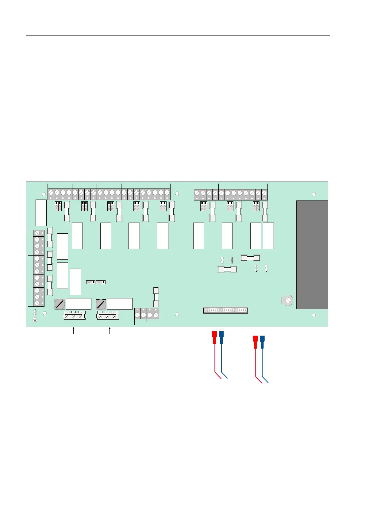
17.3 Power supply unit board and relay board
The combined power supply unit and relay board provides the entire voltage supply as well as the switching
outputs for control and status functions of the Extinguishing Control Computer. An increased current
requirement e.g. as a result of longer cable lengths, must be compensated for if necessary by an external
voltage supply via a separate power supply unit.
Constantly monitored conditions:
• Mains failure
• Battery charge
• Battery charging, current limited
• Earth fault identification (insulation)
pot.-
free
moni-
tored
NC NO C NC NO C NC NO C NC NO C NC NO C NC NO C NC NO C NC NO C
REL 8 REL 7 REL 6 REL 5 REL 4 REL 3 REL 2 REL 1
GND 24V
UBEXT
NC NO C
REL 12
NC NO C
REL 13
NC NO CNC NO C
NC NO C
REL9
REL10REL11
+
-
+
-
battery1
battery2
F5 F6 F9 F10 F11 F12 F13 F16
F15
F14
battery 1
battery 2
F10
F2
F3
F4
F1
F7
to zone card
Poti
Power supply- and relay card
mains voltage relays
230V AC
emergency operation
pot.-
free
moni-
tored
pot.-
free
moni-
tored
pot.-
free
moni-
tored
pot.-
free
moni-
tored
pot.-
free
moni-
tored
pot.-
free
moni-
tored
pot.-
free
moni-
tored
Fig. 28: Power supply unit and relay board / position of the subassemblies
 Loading...