15
17
19
21
23
25
27
29
31
33
35
37
39
41
43
45
47
16
18
20
22
24
26
28
30
32
34
36
38
40
42
44
46
48
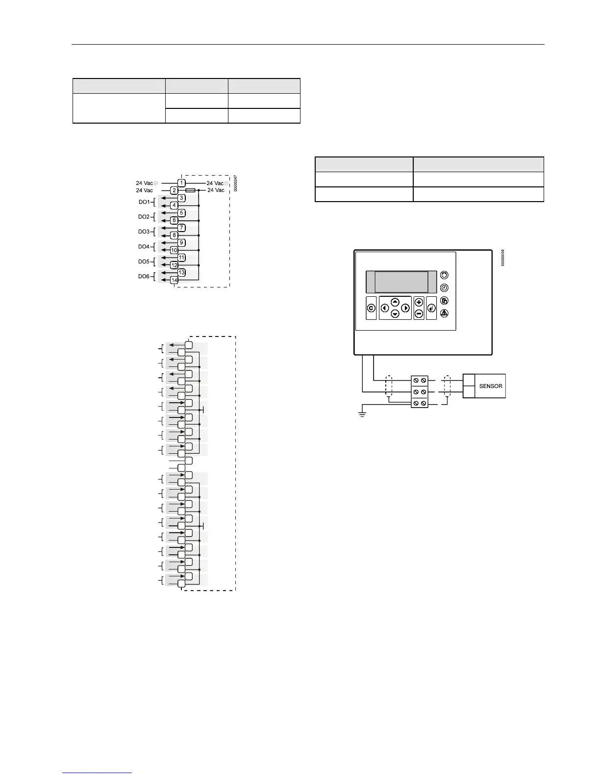
Fig. 17. Screw Terminal Block B
NOTE: The output (18...30 Vdc) of terminal 32 in screw
terminal block B is not stabilized. If you wish to
connect terminal 32 to a digital input via a potential-
free relay, see Fig. 26 on page 15.
Cabling
Cable Routing
All signal (input/output, low voltage) cables are communi-
cation circuits in accordance with VDE 0100, VDE 0800 and
local regulations and should therefore be routed separately
from line voltage.
Table 3. Min. distances to line voltage
cable type min. distance
unshielded cable 4 in. (100 mm)
shielded cable 3/8 in. (10 mm)
IMPORTANT
Avoid joining sensor cables.
Shielding
Fig. 18. Sensor shielding
Shielding of sensor and actuator cables with low protective
voltages is not necessary if the general guidelines on cable
routing are observed (see "Cable Routing", page 11). If these
guidelines cannot be observed, shielded cable must always
be used. The shielded cable must be grounded as shown in
Fig. 18.
IMPORTANT
Shielding of I/O cables that are connected to
peripherals such as sensors and actuators must be
grounded at the control cabinet side, only; this is in
order to avoid ground loops.
All Honeywell actuators are RFI suppressed in accordance
with VDE 0871/B and VDE 0875/N.
Lightning Protection
Please check with your local Honeywell representative for
information on lightning protection.

 Loading...