EXCEL 50 INSTALLATION INSTRUCTIONS
17 EN1B-0101GE51 R1105D
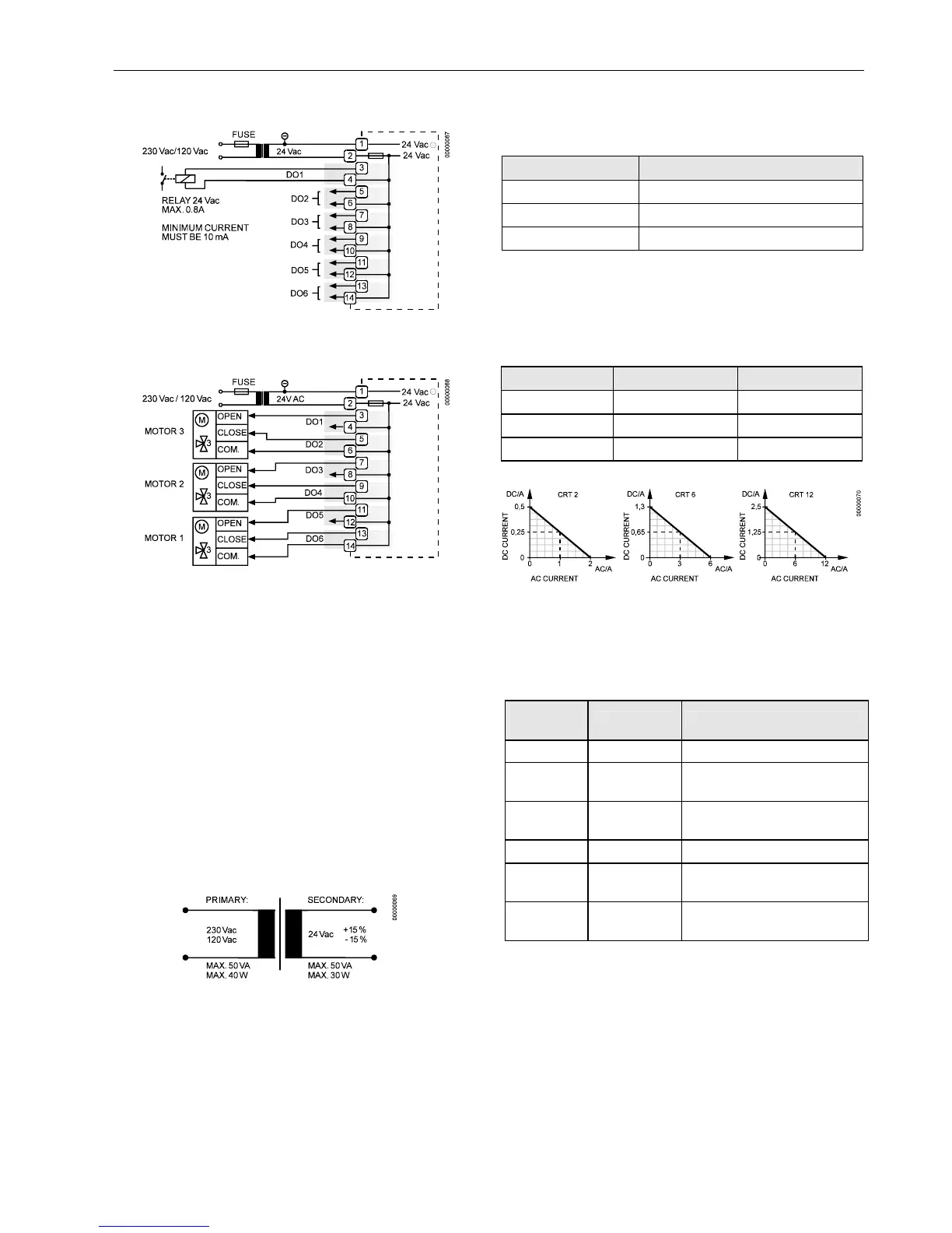
Connection Examples
Fig. 29. Digital outputs, connection of relay
Fig. 30. Digital outputs, direct connection of 3-position
actuators
Power Supply
The Excel 50 Controller is powered by an external trans-
former.
Transformer requirements for one Excel 50 Controller:
Voltage 24 Vac ±20%
Current 3 A, if fully equipped (6 DO's x 0.4 A)
2 A, if current of DO's does not exceed 1.8 A
Power 72 VA, if fully equipped
The transformer, already installed in the cabinet, can be used
to supply several controllers, communication devices or peri-
pherals (actuators, etc.) if the transformer provides sufficient
power.
Fig. 31. Transformer example
CRT-Series
Table 12. No. of controllers connected to one transformer
transformer Excel 50 controller
CRT 2 1 (1.8 A max.)
CRT 6 2
CRT 12 4
Use quick-acting backup fuse 10 A (or automatic H16 or L16)
to protect the transformer primary side. On the primary side of
the CRT 2, there is a fusible output of type M 0.315 A (T)
250 V for the purpose of fine fusing.
Table 13. Overview of CRT Series AC/DC current
transformer max. AC current max. DC current
CRT 2 2 A 0.5 A = 500 mA
CRT 6 6 A 1.3 A = 1300 mA
CRT 12 12 A 2.5 A = 2500 mA
Fig. 32. AC/DC current graphs
1450 Series
Table 14. 1450 Series transformers
part #
1450 7287
primary side secondary side
-001 120 Vac 24 Vac, 50 VA
-002 120 Vac
2 x 24 Vac, 40 VA and 100 VA
from separate transformer
-003 120 Vac
24 Vac, 100 VA and 24 Vdc
600 mA
-004 240/220 Vac 24 Vac, 50 VA
-005 240/220 Vac
2 x 24 Vac, 40 VA and 100 VA
from separate transformer
-006 240/220 Vac
24 Vac, 100 VA and 24 Vdc,
600 mA
All transformers of the 1450 series are designed for 50/60 Hz
AC and have insulated accessory outputs. The transformers
include built-in fuses, line transient/surge protection and AC
convenience outlets and meet NEC class 2 requirements.

 Loading...