EXCEL 50 INSTALLATION INSTRUCTIONS
EN1B-0101GE51 R1105D 12
Cable Lengths and Cross Sectional Areas
Table 4. Signal types and cross-sectional areas
cross-sectional area
type of signal
≤ 300 ft
(100 m)
≤ 550 ft
(170 m)
≤ 1,300 ft
(400 m)
Power supply
(24 Vac)
≤ 16 AWG
(≥ 1.5 mm
2
)
≤ 14 AWG
(≥ 2.5 mm
2
)
-
Low-current
signals*
≤ 20 AWG (≥ 0.5 mm
2
)
*E.g. for 0...10 V sensors, totalizers, digital inputs, 0...10 V
signals for actuators.
IMPORTANT
The max. length of a signal cable with 24 Vac supply
is 550 ft (170 m). The max. length of a two-wire,
0...10 Vdc signal cable is 1,300 ft (400 m). The
secondary side of the transformer must not be
connected to earth ground.
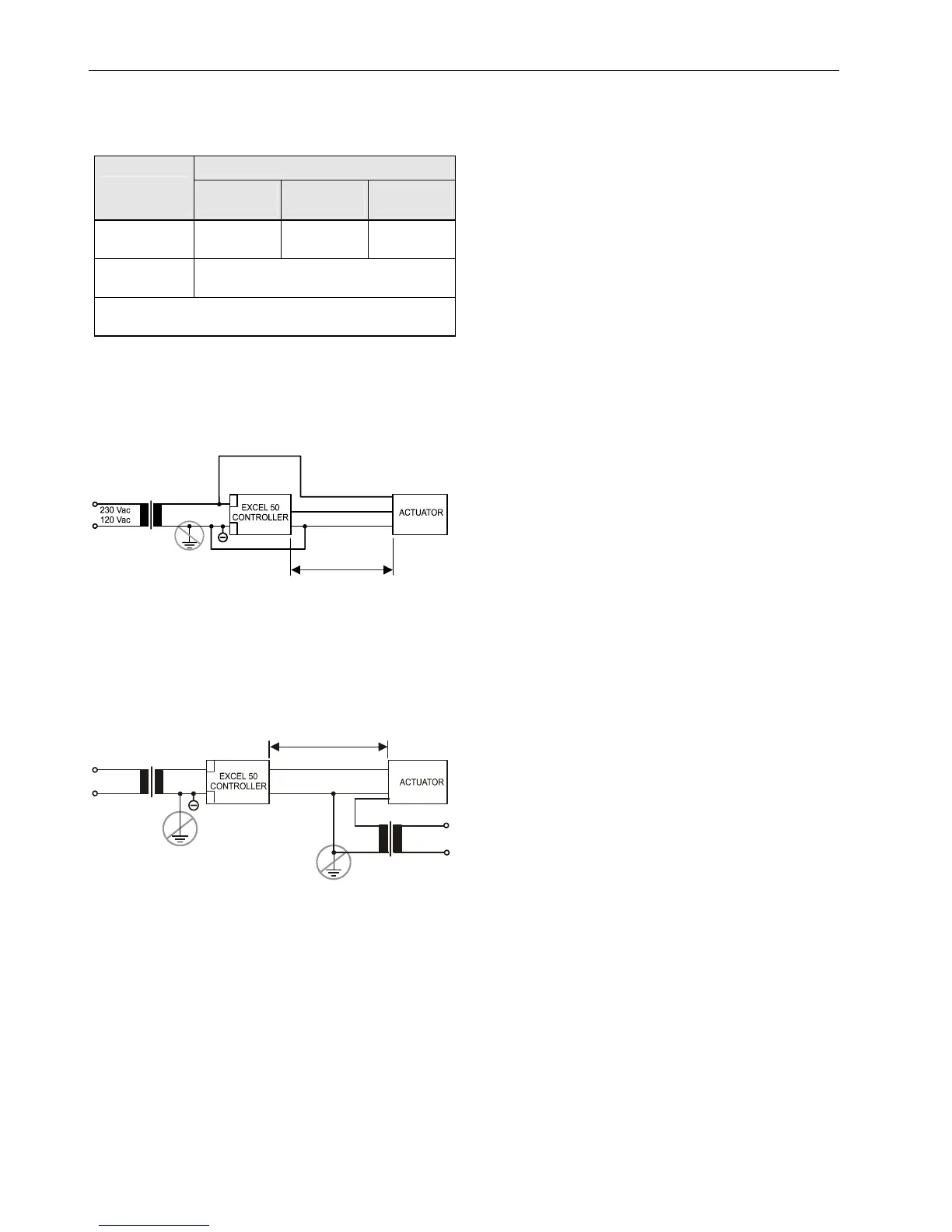
TRANSFORMER
MAX. 550 ft (170 m)
MIN. 14 AWG (2.5 mm )
2
PRIMARY
VOLTAGE
Y
GND
24 Vac
2
24 V
1
0000056
2
1
Fig. 20. Cabling of actuator with 24 Vac supply from
external transformer and max. 1,300 ft (400 m)
IMPORTANT
We recommend installing a fuse on the secondary
side of the transformer in order to protect the devices
against miswiring.
Analog Inputs
Technical Description
The analog inputs convert data from passive sensors and
active sensors with voltage output. The analog inputs can be
used as current inputs for active sensors, but then an external
resistor parallel to the sensor is necessary. It is also possible
to feed digital signals to the analog inputs (see also section
"Sensors and Transducers" on page 14.
Technical Specification
Number: Eight analog inputs
Types of input signals:
NTC 20 kΩ
0 to +10 V (max. +11 V)
0 (4) to 20 mA (with an external resistor of 499 Ω ±0.25%
[see Fig. 22])
Each input is switched automatically via software either as
input for NTC 20 kΩ (low impedance) or voltage source
0...+10V (max. +11 V, high impedance).
NTC 20k ohms: Range = -58 … +302 °F (-50 … +150 °C)
Voltage source: Range = 0...10 V
IMPORTANT
The analog inputs are protected against short circuit
and overvoltage up to 24 Vac and 40 Vdc. If any
input is sourced with more than 40 Vdc or negative
voltage, the other inputs will be influenced. This
could result in wrong values.
Passive sensors (NTC 20k ohms)
Room temperature sensor RF 20
Inlet temperature sensor VF 20A
External temperature sensor AF 20
Active sensors (0...10 V):
Duct Humidity Sensor H7011A1000
Duct Humidity Sensor H7012A1009
Active sensors (0 (4) to 20 mA):
Immersion temperature sensor VF 100
Air duct temperature sensor LF 100
Wind sensor:
Wind sensor WS21
Further connections:
Temperature sensor terminal TF26
Solar Sensor SAF 25
VMP Feedback Potentiometer
The characteristic curves for other types of sensors can be
entered manually in the data point description (see Excel 50
User Guide, EN2B-0137GE51).

 Loading...