EXCEL 50 INSTALLATION INSTRUCTIONS
EN1B-0101GE51 R1105D 28
Max. line-in/out cable length 2 m (e.g. modified NOKIA
2110 for M20T)
Protection fuse 1 A, fast blow
Max. RF power 2 W at 900 MHz
Power supply connector 6-pin modular
CE conformity:
• 89/336/EC (EMC guideline)
• 73/23/EC (Low voltage guideline)
• 91/263/EC (Telecommunications devices guideline)
Standards:
• EMC: ETS 300 342-1
• Safety: EN 60950
• GSM network: TBR 19, TBR 20
Serial Cable
For connecting the M20T to the Excel controller, a standard
RS232 cable (9-pin V24 sub-D sockets) is required.
GSM Antenna Requirements
All major suppliers of GSM antennas can supply GSM900
Antennas with FME plugs to connect with the M20 Terminal
for a variety of applications. Some antenna examples are
shown below. The antenna must satisfy the following
electrical requirements:
Antenna electrical requirements:
Frequency TX 890-915 MHz
Frequency RX 935-960 MHz
Impedance 50 Ω
VSWR TX: max. 1.7:1 installed
VSWR RX: max. 1.9:1 installed
Gain > 1.5 dB referenced to λ/2
dipole
3dB width of cone vertical: 80°
horizontal: 360°
Max. power: 1 W (cw), 2 W peak; at
ambient temperature of 55 °C
Depending on the application and the RF field at the local
site, the GSM antenna may be mounted directly or via cable.
The max. antenna cable length is 8.0 m (including 20 cm M20
Terminal-cable)
NOTE: The max. number of push/pull cycles shall not
exceed 100.
The antenna interface connector of the M20 unit is an FME
connector (of type SMR nano (male)). Hence, the connector
on the GSM antenna or antenna cable has to be of type SMR
nano (female, or use a double female connector in between).
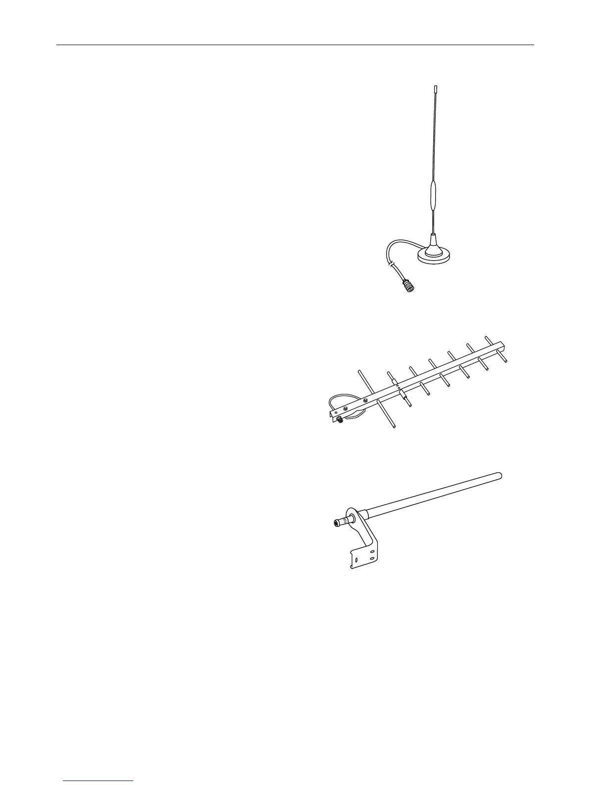
Antenna Examples
Fig. 45. Round radiation antenna, magnetic base, 5 DBi
Fig. 46. Directional antenna (YAGI), 12 DBi
Fig. 47. Round radiation antenna, 6.5 DBi

 Loading...