EXCEL 50 INSTALLATION INSTRUCTIONS
15 EN1B-0101GE51 R1105D
Digital Inputs
Technical Description
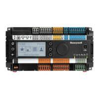
Fig. 25. Input switching voltages
The digital inputs signals can be DC voltage signals. If an
input voltage is higher than 5 V, the digital signal switches to
logic "1" status. With a hysteresis of 2.5 V, the input signal
must fall below 2.5 V before the digital status switches to logic
"0".
Three out of four digital inputs can be used as totalizers.
With V2.04.00 and higher firmware, the online point attribute
"Normally Open / Normally Closed" (NO/NC) defines the
relation between the physical state (open/closed) and its
logical status. See Table 7.
Technical Specification
Number: 4 digital inputs
Type of signals: DC signal (max. 24 Vdc)
Input resistance: 10k Ω
IMPORTANT
The digital inputs are protected against short circuit
and overvoltage up to 24 Vac and 40 Vdc.
Parameter requirements:
If the digital inputs are used for normal digital or analog
signals, the signals must meet the static and dynamic
requirements stated in Table 7 and Table 8.
If three out of four digital inputs are used as totalizers, the
signals at the totalizer inputs must fulfill the static and
dynamic requirements stated in Table 7 and Table 9 while the
signal at the fourth input must meet only the static re-
quirements of Table 7.
Table 7. Static parameters of digital inputs
contact
position
NO/NC
attribute
logical status input voltage
open NO 0
≤ 2.5 V
closed NO 1
≥ 5 V
open NC 1
≤ 2.5 V
closed NC 0
≥ 5 V
Table 8. Dynamic parameters of digital inputs
frequency
pulse
duration
pause
interval
bounce time
max. 0.4 Hz min. 1.25 s min. 1.25 s max. 50 ms
Table 9. Dynamic parameters of totalizers
frequency
pulse
duration
pause
interval
bounce time
max. 15 Hz min. 20 ms min. 30 ms max. 5 ms
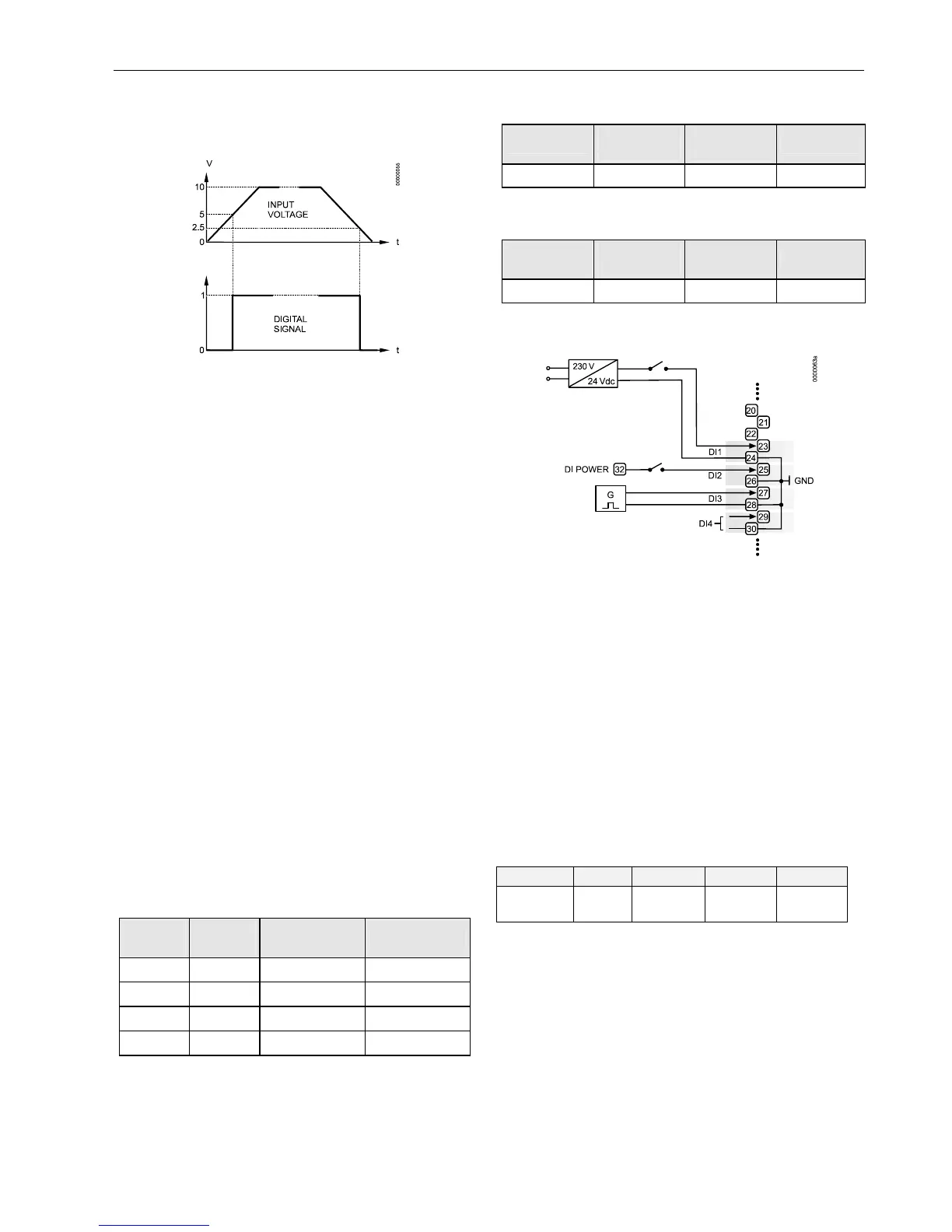
Connection Examples
Fig. 26. Digital inputs, connection examples
Analog Outputs
Technical Description
Analog outputs can be used, for example, to operate valve or
damper actuators. The characteristic curves for these
actuators can be defined via MMI (see Excel 50 User Guide).
Each analog output can also be used as a digital output.
Technical Specification
Number: Four analog outputs
Analog output details:
Table 10. Technical specifications of analog outputs
voltage current resolution min. step accuracy
0...10 V,
max. 11 V
max.
1 mA
8-Bit 0.043 mV
±100 mV
±1 digit
Relay Modules
The relay modules facilitate the control of peripheral devices
with high load via the analog outputs of the controller. The
connection examples (for the relay modules MCD 3 and
MCE 3) are shown here.
IMPORTANT
The external supply of the relay modules must be
24 Vac, the same as of the supply of the controllers.

 Loading...