EXCEL 50 INSTALLATION INSTRUCTIONS
EN1B-0101GE51 R1105D 16
The analog outputs are protected against overvoltage
up to 24 Vac and 35 Vdc.
Supply:
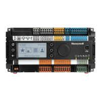
Several relay modules can be connected in series via the
bridged terminal pair:
24 Vac: Terminals 11/12 of the relay
24 Vac (-): Terminals 13 to 16 of the relay
Fig. 27. Analog outputs, connection of relay MCD 3
MCD 3:
Relay terminal 17 controls the changeover contact K3.
Relay terminal 18 controls the ON contacts K1, K2.
Ground can be looped through terminals 2/3.
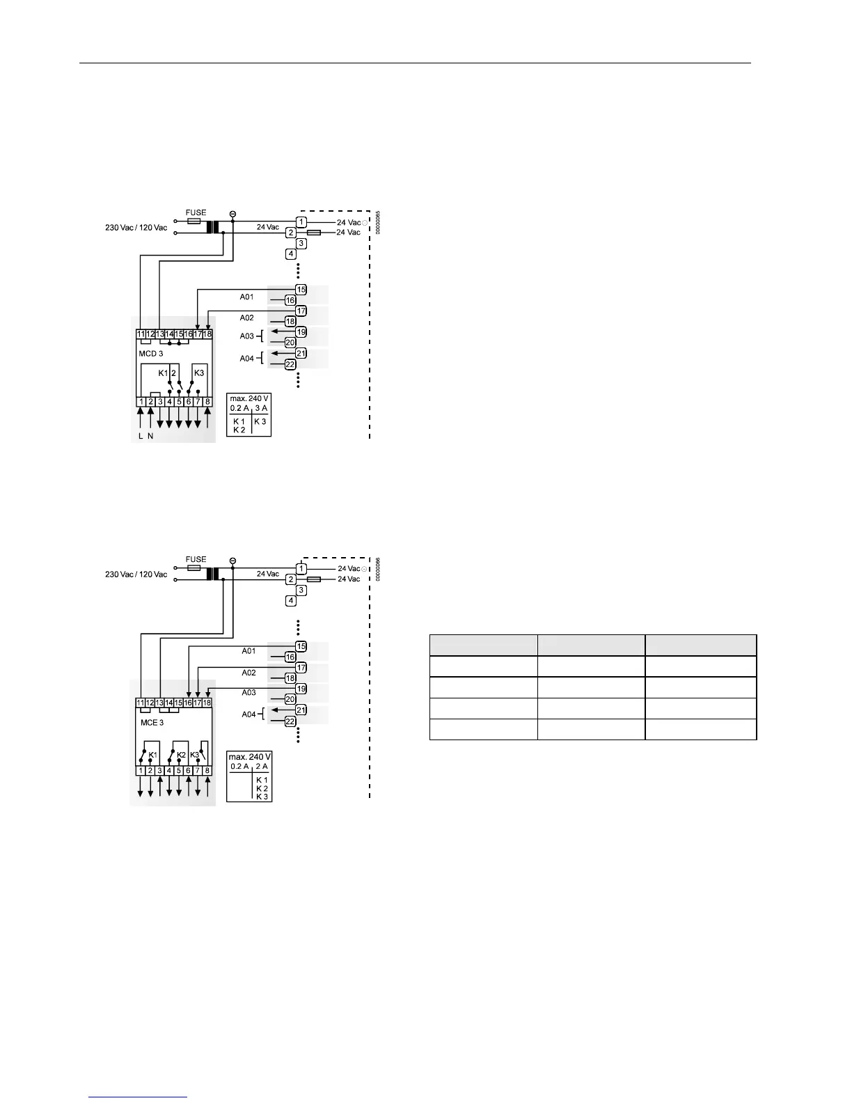
Fig. 28. Analog outputs, connection of relay MCE 3
MCE 3:
Relay terminal 16 controls the ON contact K3.
Relay terminal 17 controls the changeover contact K2.
Relay terminal 18 controls the changeover contact K1.
Digital Outputs
Technical Description
The digital outputs are switched by a triac that can be
connected directly to an external relay.
Technical Specification
Number: Six digital outputs
Output stages:
Low signal 0 V
High signal 24 Vac
Type Close, only
Load:
Per output min. 0.01 A
max. 0.8 A
Total max. 2.4 A
Cos ϕ 0.5 to 1
IMPORTANT
The digital outputs are protected against short circuit
current via internal fuse, but they are not protected
against overload. All digital outputs are protected via
only a single fuse; if any digital output is short-
circuited, the fuse will be blown and will interrupt the
main power. In that case, the controller does not
work. If the CPU is running into the WATCHDOG as
a result of a software or hardware error, all digital
outputs will be set to low signal, which means all
digital outputs are inactive.
Beginning with V2.04.00 firmware, the online point attribute
"Normally Open / Normally Closed" (NO/NC) defines the
relation between the physical state (relay ON/OFF) and its
logical status. See Table 11.
Table 11. Digital output parameters
relay ON/OFF NO/NC attribute logical status
ON NO 1
OFF NO 0
ON NC 0
OFF NC 1

 Loading...