EXCEL 50 INSTALLATION INSTRUCTIONS
EN1B-0101GE51 R1105D
38
APPENDIX 1: SMOKE CONTROL MODE
Smoke Control Configuration
1
8
11
4
9
5
3
7610
12
2
UL-listed Fire Alarm
Control Unit
Firefighters Smoke
Control Panel (FSCS)
14505068 audible
annunciator
XBS/XBSi/EBI
supply
fan
exhaust
fan
C-BUS
status control
AO
AO
AO
damper
verification
airflow
sensor
Excel 50, 100, 500, 600 Controller or LonWorks I/O
L3
L1
L6
L4 L2
L5
GND
signal line
signal line
common
earth
ground
GND
R6
2.2 ohm
CR6
20V
CR4
75V
CR3
75V
CR1
13V
CR2
10V
CR5
75V
R5
2.2 ohm
R4
2.2 ohm
R2
2.2 ohm
R3
2.2 ohm
W1
schematic diagram of 14502412-010 transient protector
equipment side
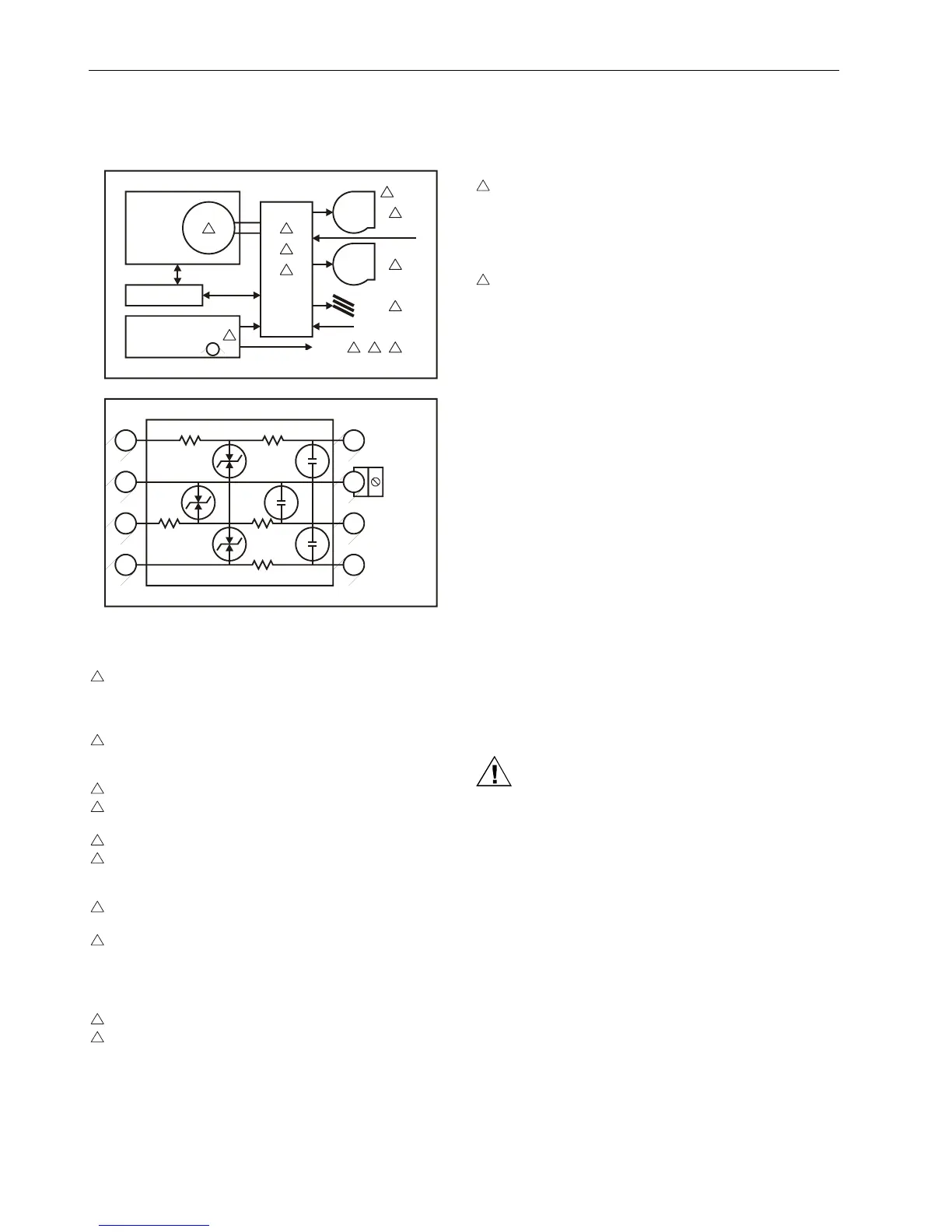
Fig. 52. Typical smoke control configuration
NOTES:
1
Locate and configure per NFPA 92A Section 3-4.3.4.
UL-listed annunciator / FSCS panel switches have a
min. rating of 24 V, 0.1 A, and lamps/LEDs have a
rating of 24 V, limited to 50 mA.
2
Locate to minimize control wiring and piping. Avoid
running wires or piping through areas that have a
high fire risk.
3
Locate per UL 555S.
4
Locate separate from and below all building exhaust
fans and upstream of any prevailing winds.
5
Exhaust to outside of building.
6
Locate airflow differential switch per CLEAFS405 and
CLEAFS460 Airflow Differential Switches Installation
Instructions 95-6001.
7
Locate UL-listed damper pressure / position indicator
per damper installation instructions.
8
Smoke control must be initiated by a listed fire alarm
control unit or in zone automatic alarm devices and
not devices located outside of the smoke control
zone interconnecting wiring must be within 20 feet (6
meters) and in conduit.
9
Refer to Smoke Control Fundamentals 77-1134.
10
Verify that the AC voltage source connected to inside
of main line voltage terminal block is from a UL 1481-
listed uninterruptible power supply. The main line
voltage terminal block max. current draw is 0.5 A. For
220/240 Vac (50/60 Hz) applications, verify that no
potential between any conductor and earth ground
exceeds 150 Vac. See Table 14 for 1450 power
supply to be used.
11
All external field wiring must be limited to 3277 feet
(999 meters) and be terminated to 14506944-001
transient protector (35 V, 290 mA max.) except C-
bus field wiring communicating at 1 MHz, which uses
14502412-010 transient protector (19 V, 500 mA. AI
on Excel 50 does not require protector.
12
Distributed LONWORKS I/O (Distributed I/Os) wiring
must be in the same enclosure or less than 20 feet
(6 meters) from the adjacent enclosure. No pro-
tection is required.
Data File Set-Up
Generate the (Excel CARE) data file for the Excel 50 (non-
MMI model), 100, 500, or 600 Controllers. This data file has a
mix of hardware points for the necessary inputs and outputs
to control fans, dampers, and other equipment. In addition to
the inputs and outputs, a customer-control program is written
to control the outputs per the sequence. The Excel 500/600
controllers can reset the program once the data from the
operator interface indicates a normal condition for the
dedicated smoke control equipment. Wire conditions must be
programmed to provide annunciation of trouble conditions.
Also required for a dedicated application for the Excel 50,
500, or 600 Controller is a weekly time program to test control
points, fans, and dampers by exercising the equipment and
verifying feedback automatically during low building activity
periods. The XL 100CUUKL is for non-dedicated smoke
control.
Panel Reset
Wen in the smoke control mode, panel reset is accomplished
by resetting the initiating panel contact circuit or by separating
the initiating/reset switch on the FSCS panel.
CAUTION
Equipment damage hazard.
Failure to use listed/approved replacement parts can
damage the product, degrade operation, and result in
loss of safety function.
This product must be installed and operated within its
environmental, mechanical, and electrical speci-
fications as contained in this document.
When servicing, use only listed/approved replace-
ments parts ordered directly from the manufacturer.

 Loading...