31
Mounting and Connection Instructions Reader series "luminAXS"
4.2.2 Parameterisation overview
4.2.3 Change interface from RS-485 to Clock/Data with MIFARE readers
State of delivery: RS-485
Change interface from RS-485 to Clock/Data with IQ DeviceInstaller and configuration tool usb.
4.2.4 Buzzer actuation with Clock/Data readers
With IQ DeviceInstaller and configuration tool usb it is possible to use one of the LED signals to
actuate the buzzer.
The LED and buzzer are actuated in parallel.
4.3 Hardware-based LED control with Clock/Data readers
The LEDs are actuated via the corresponding inputs with a low potential:
- LED green
- LED yellow
- DUO LED red (green is not possible)
The actuation should be either with an "open collector" output or with a TTL level (a protective circuit
from 6 V DC is located at the inputs).
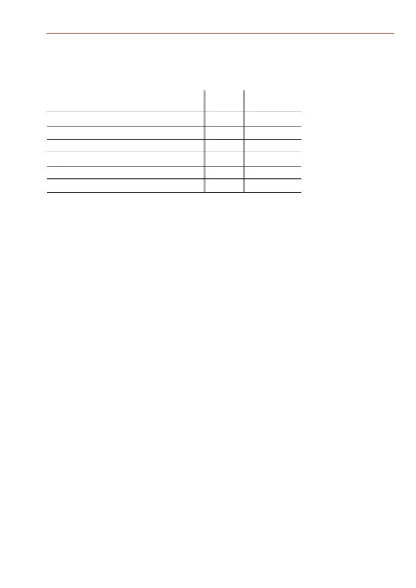
Examples for the parameterisation (extract from the options):
RS-485 Clock/Data
- Address allocation X
- Light ring colour and brightness X X
- Light ring display function X X
- TKeypad background lighting X X
- Change interface from RS-485 to C/D X*)
- LED input to the buzzer activation X
- Firmware Update X X
*) = only MIFARE readers
 Loading...