Figures
Revision 3 MC Toolkit (MCT404) User Manual xi
Figures
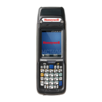
Figure 1-1 MCT404 Ruggedized and Zone 1 Intrinsically safe models .......................... 2
Figure 2-1 Honeywell ST 3000/ ST 800 Smart Transmitter - Analog mode .................... 6
Figure 2-2 Honeywell Analog Value Scaling ................................................................... 8
Figure 2-3 Honeywell DE Mode Value Scaling.............................................................. 10
Figure 2-4 Honeywell (HART) Transmitter Diagram...................................................... 11
Figure 2-5 HART Point-point and Multi-Drop Value Scaling ......................................... 11
Figure 3-1 MCT404 assembly ....................................................................................... 16
Figure 3-2 Start Menu .................................................................................................... 20
Figure 3-3 Connecting to a device through MCT404 .................................................... 21
Figure 3-4 MCT404 terminal connections to HART/DE device ..................................... 22
Figure 3-5 MCT404 terminal connections to HART Device .......................................... 22
Figure 3-6 Virtual keypad ............................................................................................... 23
Figure 3-7 Block Recognizer ......................................................................................... 24
Figure 3-8 Letter recognizer .......................................................................................... 25
Figure 3-9 Freehand recognition ................................................................................... 26
Figure 3-10 Alphanumeric keypads ............................................................................... 27
Figure 4-1 Generic layout of user interface ................................................................... 29
Figure 4-2 FDC homepage ............................................................................................ 30
Figure 4-3 Device homepage ........................................................................................ 38
Figure 4-4 Device configuration screen ......................................................................... 41
Figure 5-1 Menu Tree - Honeywell DE Displays ........................................................... 72
Figure 5-2 Offline Browse / Open File dialog ............................................................... 100
Figure 5-3 MC Toolkit Options ..................................................................................... 101
Figure 5-4 DE device ................................................................................................... 102
Figure 5-5 STT25D and 25M, STT350 models ........................................................... 103
Figure 5-6 STT25T model ............................................................................................ 103
Figure 5-7 ST 3000 / ST 800 models .......................................................................... 103
Figure 5-8 STT25M and 25D models .......................................................................... 104
Figure 5-9 ST3000 DE ................................................................................................. 104
Figure 5-10 DE STT350 ............................................................................................... 104
Figure 5-11 Save As File dialog .................................................................................. 105
Figure 5-12 Honeywell DE Save Template Screen ..................................................... 106
Figure 5-13 Offline Honeywell DE Save Template as working file .............................. 106
Figure 5-14 Download in Offline Mode ........................................................................ 107
Figure 7-1 Remove Handstrap .................................................................................... 140
Figure 7-2 Remove Battery Cover ............................................................................... 140
Figure 7-3 SD Card Replacement ............................................................................... 142
Figure 8-1 Screen Y ..................................................................................................... 143
Figure 8-2 Screen X ..................................................................................................... 145
Figure 8-3 ActiveSync/Mobile Device Center file transfer ........................................... 147
Figure 8-4 MCT404 Infrared port location ................................................................... 148
 Loading...
