ID2000 Series Operating Manual
Operator Actions at Panel
13 997-434-000-4, Issue 4
May 2010
4.7 Lamp Test and Display Control
4.7.1 Lamps Test In Sequence
To test the lamps in sequence:
1 With the Top Level menu displayed, press the ‘0’
pushbutton momentarily. The TEST menu is
displayed:
2 Press the ‘2’ pushbutton. The following occurs:
a. The panel lamps will be tested in sequence, one
row at a time being briefly illuminated.
b. The internal FIRE sounder, and then the FAULT
sounder, (but not remote sounders) will also be
tested momentarily.
c. The text display will briefly show the sign-on
message, including the product description, the
panel software version number and the Loop
Interface PCB software version number.
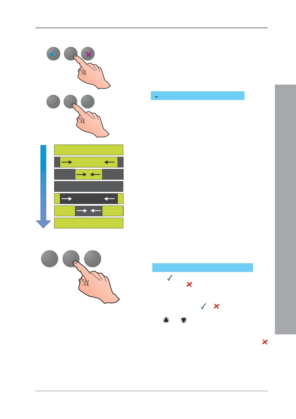
d. The text display will then show two bars which
draw from its outer edges to its centre until the
entire display is covered. The display then clears
from its outer edges to the centre. This verifies
that every pixel on the display is switching on and
off correctly.
4.7.2 All Lamps Lit and LCD Adjust
To switch all lamps on until cancelled, and adjust the LCD
display:
1 With the TEST menu displayed, hold the ‘2’
pushbutton down for approximately 3 seconds. The
following is displayed:
2 Press
; all the lamps will be switched on and will
remain on until
or RESET is pressed (see below).
This test is normally required only for factory set-up
of the panel.
3 Whether you answer or , the text display then
changes to a scrolling ‘quick brown fox’ test message.
The
and keys may now be used to adjust the
Liquid Crystal Display (LCD) contrast to suit the
viewing angle.
4 When satisfied with the display, press the
pushbutton.
If the system is running on batteries only (i.e. with a Mains/
PSU Failure indicated on the LCD and the POWER
SUPPLY FAULT lamp on), the length of time during which
the LCD display is backlit is shortened to extend the
battery support time.
TEST : 0=Zone/1=Output/2=Lamps:
1
3
1
3
Switch ALL lamps on (
!!
!!
!/X)?

 Loading...


