ID2000 Series Operating Manual
Operator Actions at Panel
30997-434-000-4, Issue 4
May 2010
4.10.1 Display and/or Log Device Data
(This function is also available from the VDU terminal)
This function is used to continuously monitor the data
value returned by a sensor or module. Values are shown
as a percentage, scaled so that a sensor’s nominal FIRE
threshold reading is 100% (i.e. if the reading is 100% or
above the sensor is in FIRE condition; if it is below 100%
it is not).
Note: These values are scaled up from an internal digital
value, therefore at some places ‘gaps’ may appear
in the scaling where the reading appears to jump
by 2%.
Other facilities available are the option to set the sensor’s
LED indicator into ‘pulsing’ mode, and to set up a memory
log of its data readout. See below for details.
To display and/or log device data:
1 From the top level display, press pushbutton ‘2’ (on
the VDU press ‘8’). If operating from the panel, the
options shown below are displayed:
2 Select option ‘0’. This step is omitted if operating from
the VDU. The options shown below are then displayed:
3 Select option ‘0’. The options shown below are then
displayed:
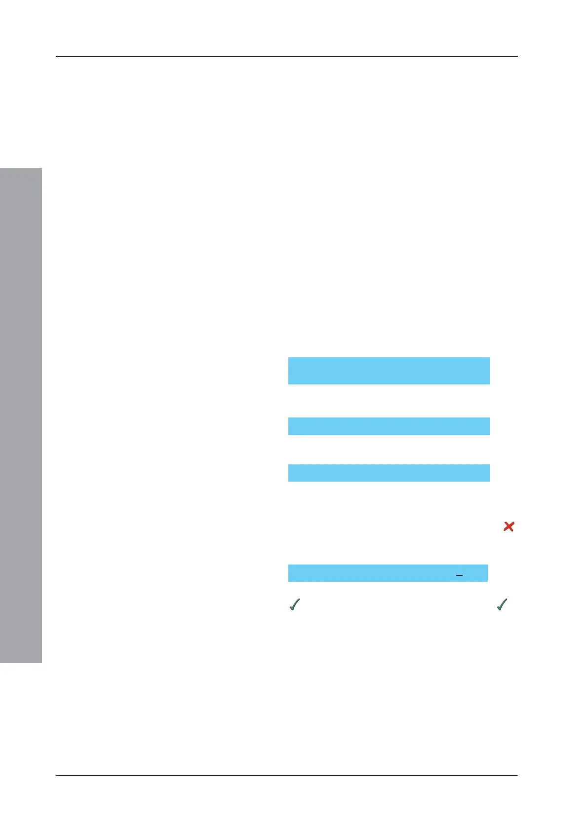
4 Press the appropriate pushbutton, depending on
whether you want to inspect Analogue sensors or
Monitor/Control modules. If after examining Sensors
you want to examine Modules, you must cancel (
)
the current operation and then re-enter it.
5 The zone select prompt is then displayed:
Key in either the specific Zone number followed by
, to examine only devices in that zone, or just to
select the default of ALL ZONES.
0=Display/1=Full Printer Dump
0=Sensor/1=Module:
Choose from ZONE no. (0 = ALL)?n
LOG/DISPLAY: 0=Devices/1=Events:
2=Printer Control:

 Loading...


