XNX Universal Transmitter
Introduction
22
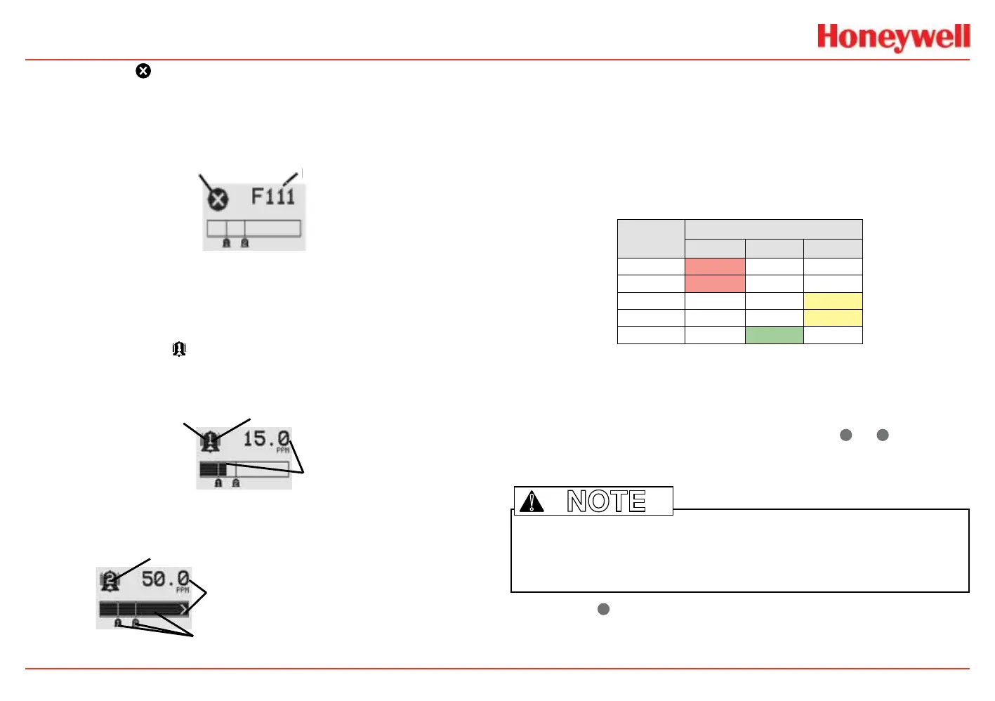
If the fault icon is displayed, a fault condition has been
triggered and the display will alternate between the target gas
concentration and the fault code. See the Warnings and Faults
section for more fault code information.
Fault Icon
Fault Code
Figure 12. General Status Fault detail
In the event of multiple warnings or faults, the user can view all
messages with the transmitter’s Event History function.
When an Alarm icon
is displayed, the target gas
concentration exceeds one or both preset alarm levels. The
General Status Screen displays the gas concentration and the
alarm level exceeded.
Target Gas
m Icon
Figure 13. General Status Alarm detail
In an overrange condition, the alarm icon will display and the target
gas concentration bar graph and alarm setpoints will ash.
Full Scale
Concentration
Concentration Bar, Alar
Figure 14. General Status Overrange detail
Negative values are not displayed and do not appear on the
4-20 mA output, but they are indicated by faults or warnings
when preset thresholds are exceeded. (See zero deviation in the
Specications section)
In addition to the graphic alarm, fault, and warning indicators,
the LEDs on the front panel ash in these patterns based on the
condition:
Condition
LED
1
Red Green Yellow
Alarm 1 Solid
Alarm 2 Flashing
Warning Solid
Fault Flashing
2
Health Flashing
1
The refresh rate of the LEDs is 0.5 second.
2
Special states (Warmup, Inhibit) are not indicated by the Fault LED.
Entering the Menu
Swiping the magnet over the magnetic switch
✓
or
✖
allows the
user to reset faults or alarms, display current settings, or make
adjustments to the device.
Note: If the Easy Reset option is set to Lock, alarms and faults cannot be reset
without logging in or entering a passcode. For more information, see the Configure
Security section.
!
Swiping the
✖
or “escape” magnetic switch activates the Alarm
Reset screen and allows alarms to be silenced and faults to be
reset.
 Loading...


