XNX Universal Transmitter
Installation and Operation
69
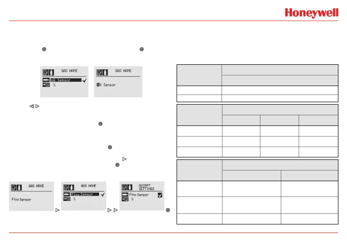
Changing the Gas or Units Name
If “Other mA Sensor” has been selected as the sensor type, the
existing gas and units can be renamed.
From the Gas Selection
menu, select
✓
to open the Gas Name menu. Select
✓
again to
open the Gas Name editing display. The rst letter of the current
selection will be highlighted (Figure 80).
Figure 80. Gas Name screen / Gas Name editing screen
Use the switches to cycle through the 76 options (26 capital
letters, 26 lower case letters, 10 numbers, 13 typographic
characters, and a space). When the rst character of the new
gas name has been reached, select
✓
to advance to the second
character. Repeat this procedure with each character until
the new gas name is displayed. In this example, “mA Sensor”
has been changed to “Flow Sensor” (Figure 83). The name
can be up to 15 characters long. Select
✓
to return to the Gas
Name screen. The new name will be displayed in reverse (light
characters on a dark background). Select the
switch twice to
display the Accept Settings screen. Select
✓
to accept the new
gas name. A “Settings Accepted” screen will be displayed briey,
followed by the Gas Selection menu.
✓
Figure 81. Accepting the New Gas Name screens
Follow the same procedure to rename the units (“%” in the
illustrations). The units name can be up to 5 characters long.
Gas Selections and Alarm Limits Based on mV Sensor
Type
These tables show the tranmsitter’s programmable alarm limits.
Note: -2 Gas Selection %LEL values are per IEC 60079-20-1:2010
Alarm Limits (% Vol)
MPD-IC1 (5%V)
Carbon Dioxide
Lower
0.5
Upper
5.0
MPD-IV1 (5%V/V, 100%LEL)
Methane Methane-1 Methane-2
Lower Alarm Limit
0.5% Vol 10% LEL 10% LEL
Upper Alarm Limit 5.0% Vol 60% LEL 60% LEL
% Volume Reference
n/a 5.0 4.4
MPD-IF1 (100%LEL)
Propane-1 Propane-2
Lower Alarm Limit
(% LEL)
10 10
Upper Alarm Limit
(% LEL)
60 60
% Volume Reference
2.0 1.7
 Loading...


