XNX Universal Transmitter
Installation and Operation
89
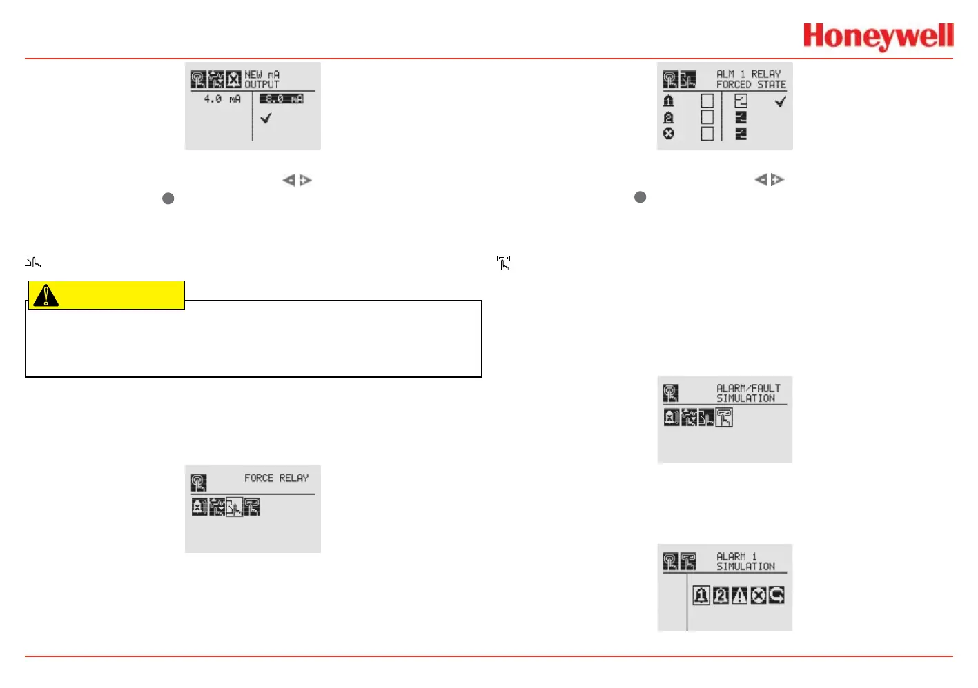
Figure 151. New mA Output screen
Once the new value is input, use the switches to move to
the ‘ü’ and use the
✓
magnetic switch on the front panel to set
the mA output.
Force Relays
Caution: Any relay conditions set in this menu will revert to the normal operating
values when exiting the Test Menu. For more information on setting the relay options
for normal operation, see Relay Options.
The Force Relay menu allows peripheral devices driven by relays
from the transmitter to be tested. Depending on the relay options
set in the Relay Options menu (see the Relay Options section), the
relay will be open or closed.
Figure 152. Force Relays screen
The Relay State screen shows the current relay conguration in
the left column. The output can be controlled by changing the
value in the column on the right.
Figure 153. Relay State screen
Once the new value is input, use the switches to move to
the ‘ü’ and use the
✓
magnetic switch on the front panel to
change the condition of the relay.
Alarm/Fault Simulation
Alarm and Fault simulation work in tandem with the previous
sections (Force mA Output and Force Relays) to allow testing of
the transmitter and the peripheral warning and safety devices.
Figure 156 shows the menu choices for selecting an alarm or
fault simulation.
Figure 154. Alarm/Fault Simulation screen
Selecting an alarm level to simulate activates a conrmation
screen.
Figure 155. Alarm/Fault Simulation menu
 Loading...


