XNX Universal Transmitter
Installation and Operation
79
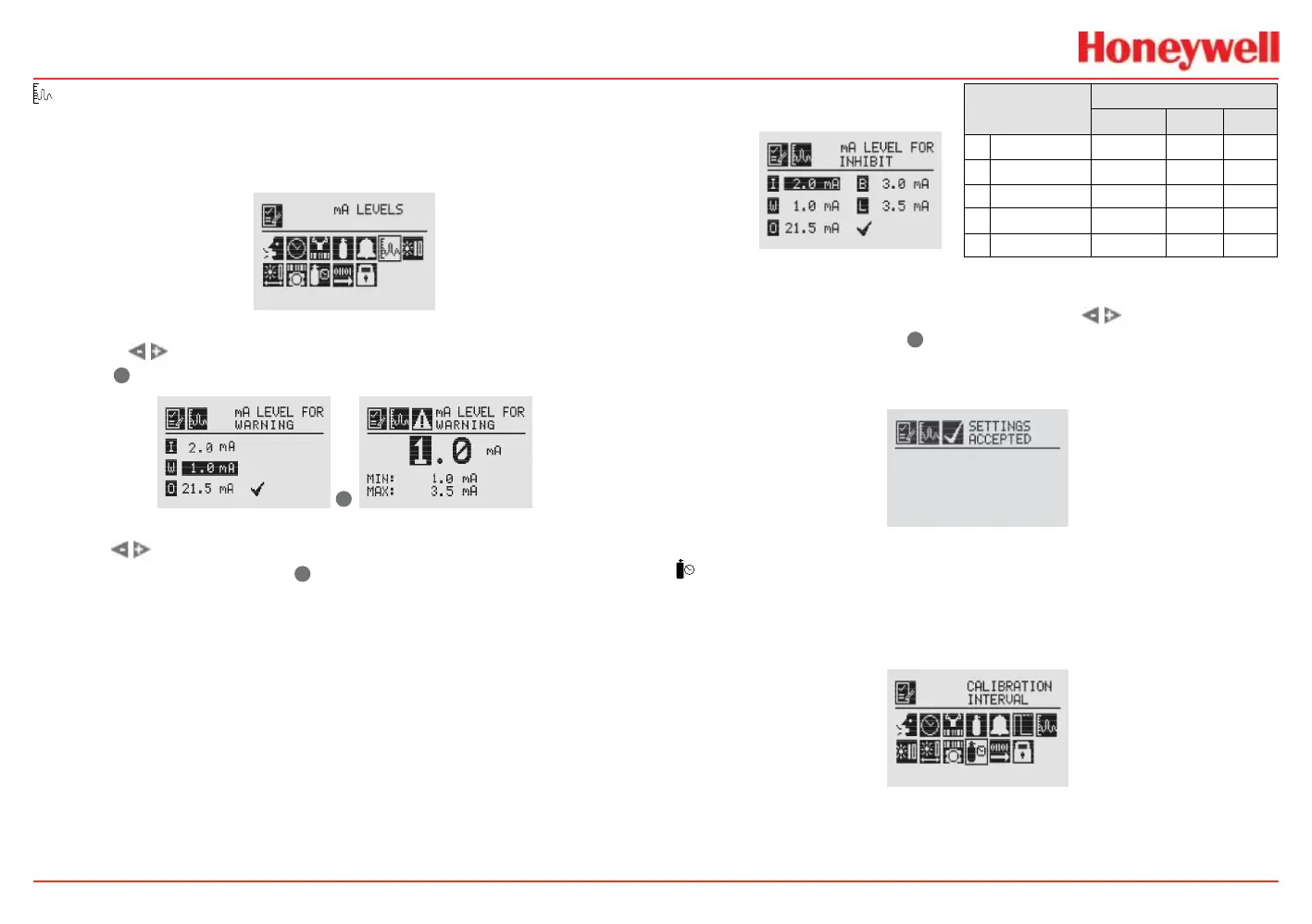
mA Levels
This option allows the user to select mA output levels for inhibit,
fault, and overrange. Beam block and low signal apply to
Searchline (see the table in the next column).
Figure 100. mA Levels menu
Using the switches, move to the mA output to be changed
and use
✓
to select it.
✓
Figure 101. Set mA Levels for Warning screens
Use the switches to decrease or increase the value until the
desired value appears. Use
✓
to select the value and move to the
next setting. Repeat for each setting to be changed.
The default values and available output ranges for Inhibit,
Warning, Overrange, Beam Blocked, and Low Signal are shown in
the following table. See Warnings and Faults for more information.
Signal
Output (mA)
Default Min Max
I Inhibit 2.0 1.0 3.5
W Warning 3.0 1.0 3.5
O Overrange 21.0 20 22
B Beam Blocked 1.0 1.0 4.0
L Low Signal 1.0 1.0 4.0
Figure 102. Set mA Levels for Inhibit screen
After all changes have been made, use the switches to
move to the ‘ü’ and use
✓
on the front panel to accept and
save the settings. If ‘ü’ is not selected, none of the changes will
be saved.
Figure 103. mA Settings Saved screen
Calibration Interval
Calibration Interval allows a desired interval for sensor
calibration to be set for sensors attached to the transmitter. The
transmitter will generate a warning when the interval is reached.
Figure 104. Calibration Interval menu
Calibration Interval will not appear when an IR personality board
is attached and the mA sensor type is set as ‘Other mA Sensor’.
 Loading...


