XNX Universal Transmitter
Installation and Operation
39
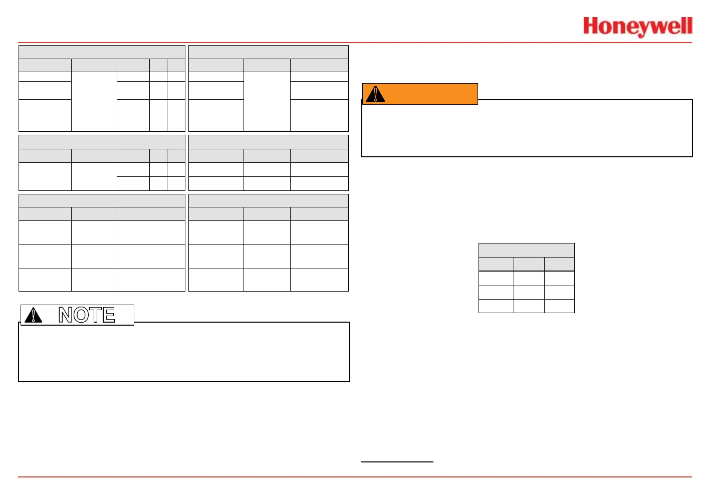
Table A Table B
Board Type Function S1 S2 Board Type Connection Function
EC Personality
4-20mA
Output
Source
EC Personality
TB1
Power, 4-20mA
mV
Personality
Sink
mV Personality
Power, 4-20mA,
Sensor
IR
Personality
Isolated
IR Personality
Power, 4-20mA,
IR Power and
Signal
Table C Table D
Board Type Function S3 S4 Board Type Connection Function
IR
Personality
IR 4-20mA
Input
Source
EC Personality J2 EC IS Barrier
Sink
IR Personality TB2 Com A and B
Table E Table F
Board Type Connection Function Board Type Connection Function
Relay TB4
Remote Reset
Connector
Relay TB3 Relay Output
Modbus SW5
Bus Loop
Terminators
Modbus TB3 Data Connection
Foundatin
Fieldbus
SW5 Simulation Mode
Foundation
Fieldbus
TB3 Data connection
Note: Open loop faults are not available due to HART, Modbus, and FOUNDATION Fieldbus
interfaces where a 4-20 signal cannot be used. In this case, open loop, 0mA must be
used as the diagnostic.
!
The Option circuit boards vary depending upon the option
selected when ordered. Only one of the three available interface
options (relays, Modbus, or FOUNDATION Fieldbus) can be
attached to the transmitter. When installed, connections to the
options are made to connectors at the bottom of the POD
.
4-20mA Output, Common Connections, and Power
Settings
The transmitter allows the user to congure the 4-20mA
output to Sink, Source, or Isolated mode operation via two
programming switches on the POD
1
. The Switch Conguration
table shows the S1 and S2 setting and corresponding output
conguration.
Switch Configuration
Mode S1 S2
Source Down Up
Sink Up Down
Isolated Down Down
Most controllers in the market will accept source-congured
devices. Sink-congured signals are used in older technology
controllers, which reduce the need for complete system
upgrades. In isolated-signal devices, if the controller fails or the
mA signal wires are disconnected or broken, the eld device will
remain operational. Most controllers in the market will accept
isolated congured devices.
Power and 4-20mA connections are made at TB-1 and are
identical for the EC, IR, and mV Personality Boards. For user
convenience, a second set of +Ve and -Ve power terminals have
been provided to eliminate the need for a secondary junction
1 The 4-20 mA output state is refreshed at least every two seconds (once per second is typical).
Warning: Power off the transmitter before changing S3 or S4. Failure to do this will
permanently damage the transmitter. Both switches must be set in either Source or
Sink prior to applying power.
 Loading...


