Optical Drive Connector Board
Description Spare part number
Optical drive connector board 643153-001
Optical drive SATA cable 643159-001
Optical drive eject/brightness cable 643146-001
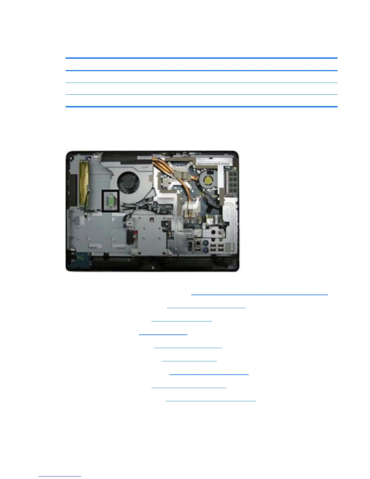
The optical drive connector board is located near the bottom left side of the fan sink. It is secured by
two screws and has one connector.
Figure 7-41 Optical drive connector board location
To remove the optical drive connector board:
1. Prepare the computer for disassembly (see
Preparing to Disassemble the Computer on page 43).
2. Remove the small rear cover (see
Small Rear Cover on page 44).
3.
Remove the port cover (see
Port Cover on page 45).
4. Remove the stand (see
Stand on page 46).
5. Remove the drive cover (see
Optical Drive on page 47).
6. Remove the memory cover (see
Memory on page 53).
7. Remove the upper rear panel (see
Upper Rear Panel on page 55).
8. Remove the I/O panel (see
Rear I/O Cover on page 67).
9. Remove the outer/left panel (see
Outer/Left Rear Panel on page 75).
10.
Remove two screws (1) that secure the board to the computer.
Optical Drive Connector Board
83
 Loading...