Component identification 13
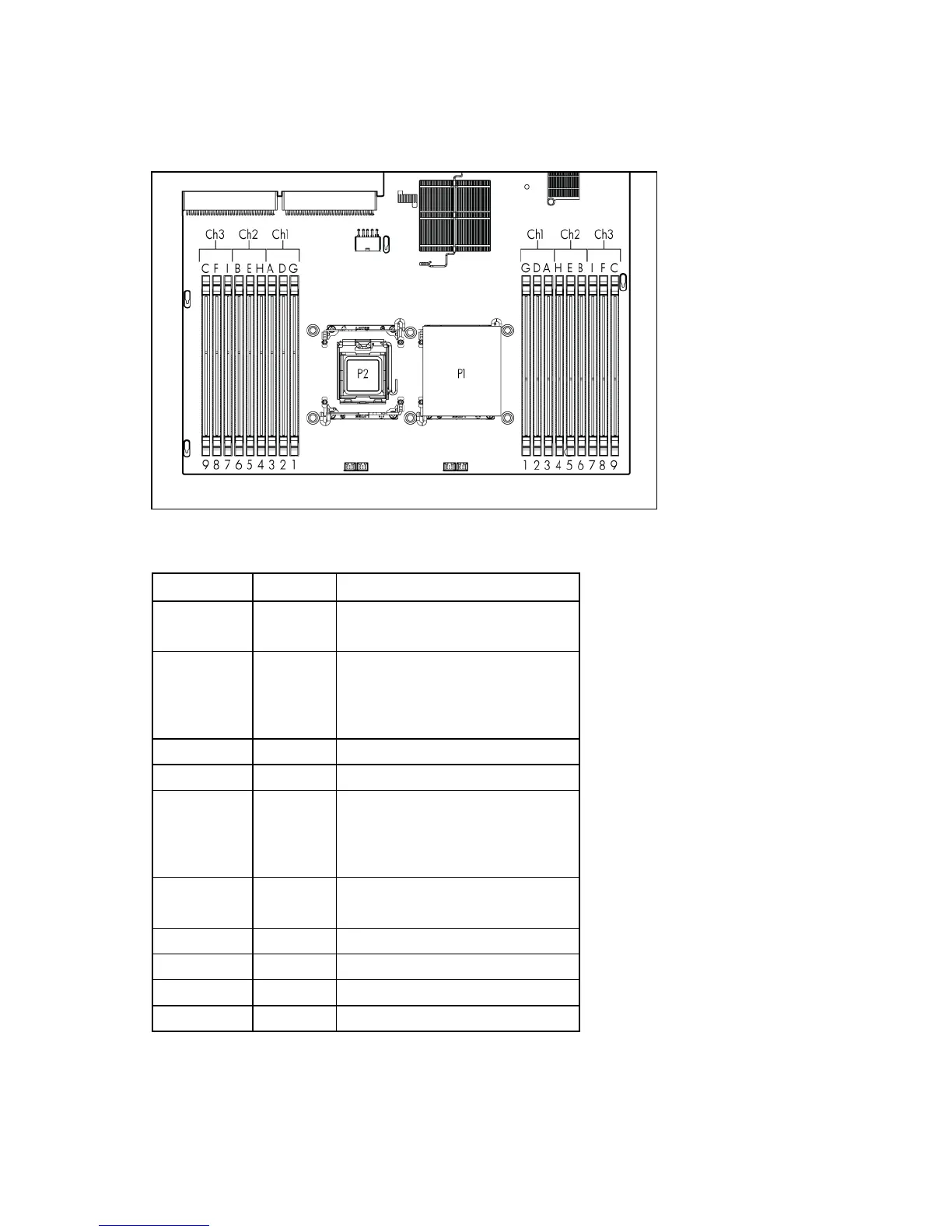
DIMM slots
DIMM slots are numbered sequentially (1 through 9) for each processor. The supported AMP modes use
the letter assignments for population guidelines.
System maintenance switch
Position Default Function
S1 Off Off = iLO 2 security is enabled.
On = iLO 2 security is disabled.
S2 Off Off = System configuration can be
changed.
On = System configuration is
locked.
S3 Off Reserved
S4 Off Reserved
S5 Off Off = Power-on password is
enabled.
On = Power-on password is
disabled.
S6 Off Off = No function
On = Clear NVRAM
S7 — Reserved
S8 — Reserved
S9 — Reserved
S10 — Reserved
When the system maintenance switch position 6 is set to the On position, the system is prepared to erase
all system configuration settings from both CMOS and NVRAM.
 Loading...