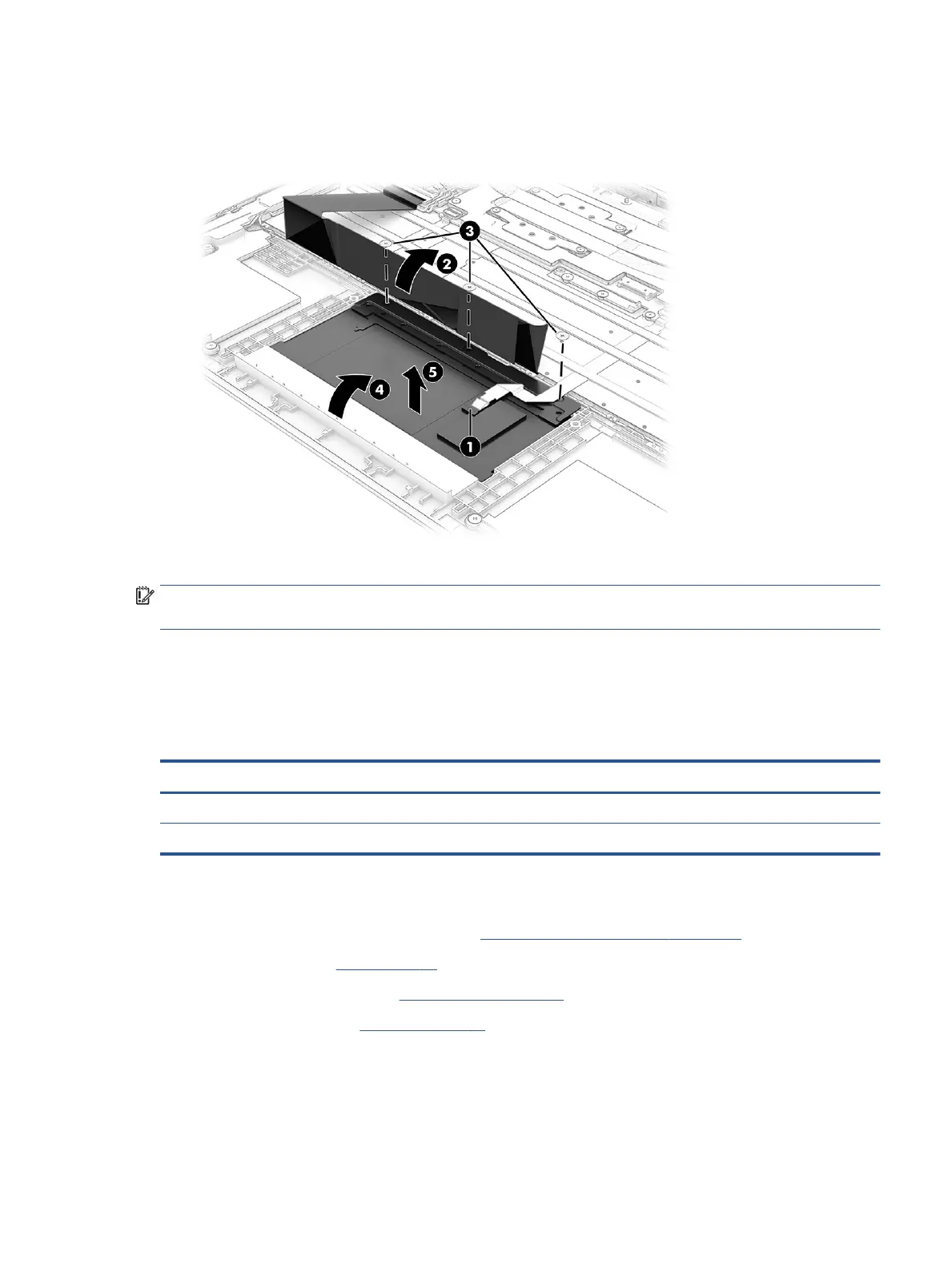
3. Remove the three Phillips M2.0 × 2.0 screws (3) that secure the touchpad to the computer.
4. Rotate the touchpad upward to a 20° to 30° angle (4), and then pull the touchpad away from the
computer at an angle to remove it (5).
Reverse this procedure to install the touchpad.
IMPORTANT: To avoid damaging the display during touchpad installation, before inserting the touchpad into
the computer, lift the top cover/keyboard up o the display.
Wireless antennas and cables (installed on top cover)
To remove the wireless antennas and cables that are installed on the top cover, use this procedure and
illustration.
Table 6-4 Wireless antennas and cables description and part number
Description Spare part number
Wireless antennas and cables (main) M35272-001
Wireless antennas and cables (aux) M35273-001
Before removing the wireless antennas and cables, follow these steps:
1. Prepare the computer for disassembly (see Preparation for disassembly on page 28).
2. Remove the pen (see Pen on page 28).
3. Remove the bottom cover (see Bottom cover on page 30).
4. Remove the battery (see Battery on page 31).
Remove the wireless antennas and cables:
1. Disconnect the antenna cables from the WLAN module (1).
2. Remove the cables from their routing under the keyboard cable and around to the left antenna (2).
Component replacement procedures 35
 Loading...