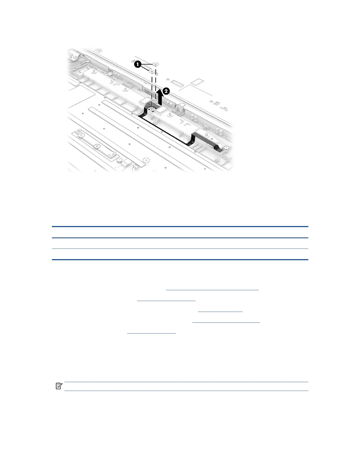
2. Peel the cable o the computer (2). The cable is secured to the computer with adhesive.
Reverse this procedure to install the POGO connector.
Antenna bar
To remove and disassemble the antenna bar, use these procedures and illustrations.
Table 6-10 Antenna bar description and part number
Description Spare part number
Antenna bar (main) M35272-001
Antenna bar (aux) M35273-001
Before removing the antenna bar, follow these steps:
1. Prepare the computer for disassembly (see Preparation for disassembly on page 28).
2. Remove the bottom cover (see Bottom cover on page 30).
3. Disconnect the battery cable from the system board (see Battery on page 31).
4. Disconnect the display cable and the sensor cable (see Display assembly on page 46).
5. Remove the heat sink (see Heat sink on page 36).
Remove the antenna bar:
1. Disconnect the antenna cables from the WWAN module (1) and the integrated WLAN module (2).
2. Remove the ve reusable rubber screw covers from the antenna bar (3).
3. Remove the ve Phillips M2.0 × 3.0 screws (4) that secure the antenna bar to the computer.
NOTE: Three of the screws are removed vertically. Two of the screws are removed horizontally.
44 Chapter 6 Removal and replacement procedures for authorized service provider parts
 Loading...