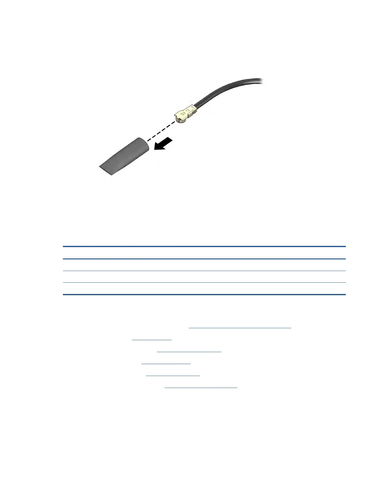
4. If the WWAN antenna is not connected to the terminal on the WWAN module, install a protective sleeve
on the antenna connector, as shown in the following illustration.
Reverse this procedure to install the WWAN module.
System board
To remove the system board, use these procedures and illustrations.
Table 6-8 System board descriptions and part numbers
Description Spare part number
System board
Includes integrated processor and 16 GB of system memory M35255-601
Includes integrated processor and 8 GB of system memory M35254-601
Before removing the system board, follow these steps:
1. Prepare the computer for disassembly (see Preparation for disassembly on page 28).
2. Remove the pen (see Pen on page 28).
3. Remove the bottom cover (see Bottom cover on page 30).
4. Remove the battery (see Battery on page 31).
5. Remove the heat sink (see Heat sink on page 36).
6. Remove the solid-state drive (see Solid-state drive on page 37).
Remove the system board:
1. Disconnect the following cables from the system board:
● WWAN antennas from the WWAN module (1)
● Display cable (2)
● POGO cable (ZIF) (3)
Component replacement procedures 41
 Loading...