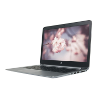
2. Remove the heat sink from the computer (2).
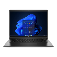
3. Thoroughly clean the thermal material from the surfaces of the heat sink and the system board
components each time the heat sink is removed. Replacement thermal material is included with the heat
sink and system board spare part kits. The following illustration shows the replacement thermal
material locations.
Thermal grease is used in one location on the heat sink (1). Thermal pads are used in six locations on the
heat sink (2).
Reverse this procedure to install the heat sink.
Solid-state drive
To remove the M.2 solid-state drive, use this procedure and illustration.
Table 6-6 Solid-state drive descriptions and part numbers
Description Spare part number
512 GB, PCIe-3 × 4, TLC M54568-005
256 GB, PCIe-3 × 4, TLC M54567-005
128 GB, PCIe-3 × 2, TLC M54569-005
Component replacement procedures 37
 Loading...