System board
NOTE: All system board spare part kits include replacement thermal material.
NOTE: System board appearance may vary.
1. Prepare the computer for disassembly (Preparation for disassembly on page 19).
2. Remove the access panel (Access panel on page 20).
3. Rotate the small bae into the upright position (Small bae on page 47).
4. Remove the fan bae (Fan bae on page 48).
5. Rotate the drive cage to its upright position.
6. When replacing the system board, make sure the following components are removed from the defective
system board and installed on the replacement system board:
●
Memory modules (Memory on page 23)
●
Expansion cards (Expansion card on page 26)
●
Heat sink (Fan sink on page 55)
●
Processor (Processor on page 56)
7. Disconnect all cables connected to the system board, noting their location for reinstallation.
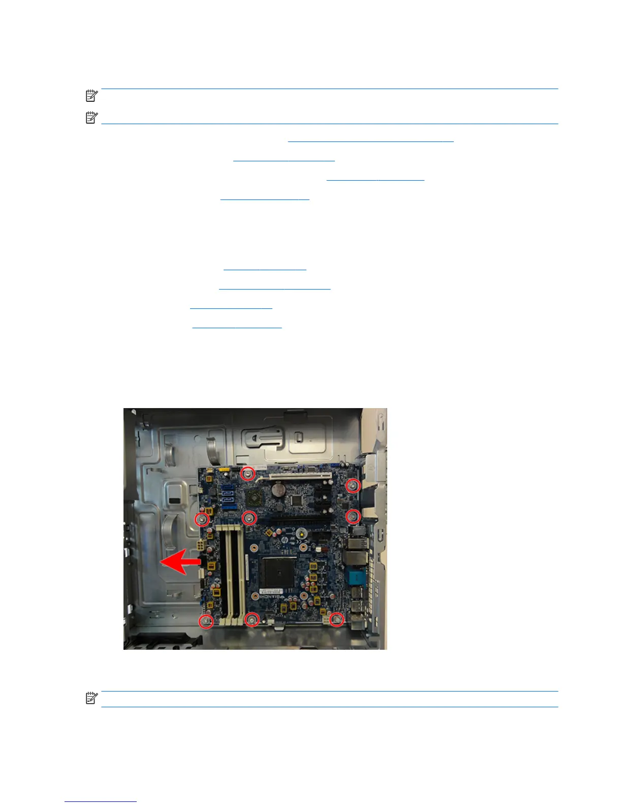
8. Remove the eight Torx T15 screws that secure the system board to the chassis.
9. Slide the system board toward the front of the computer to disengage the I/O panel, and then lift the
system board out of the computer.
When reinstalling the system board, rst insert the I/O panel back into the slots in the rear of the chassis, and
then align the board with the chassis screw holes.
NOTE: When replacing the system board, you must change the chassis serial number in the BIOS.
60 Chapter 4 Removal and replacement procedures – small form factor (SFF) chassis
 Loading...