9
Attaching the mounting brackets to the switch
1. Determine the installation position for the mounting brackets.
The HPE 5140 24G SFP w/8G Combo 4SFP+ EI, HPE 5140 24G PoE+ 2SFP+ 2XGT EI,
and HPE 5140 48G PoE+ 2SFP+ 2XGT EI switches provide two installation positions for the
mounting brackets: port side mounting position and power supply side mounting position.
The other HPE 5140 EI switches provide only the port side mounting position for the
mounting brackets.
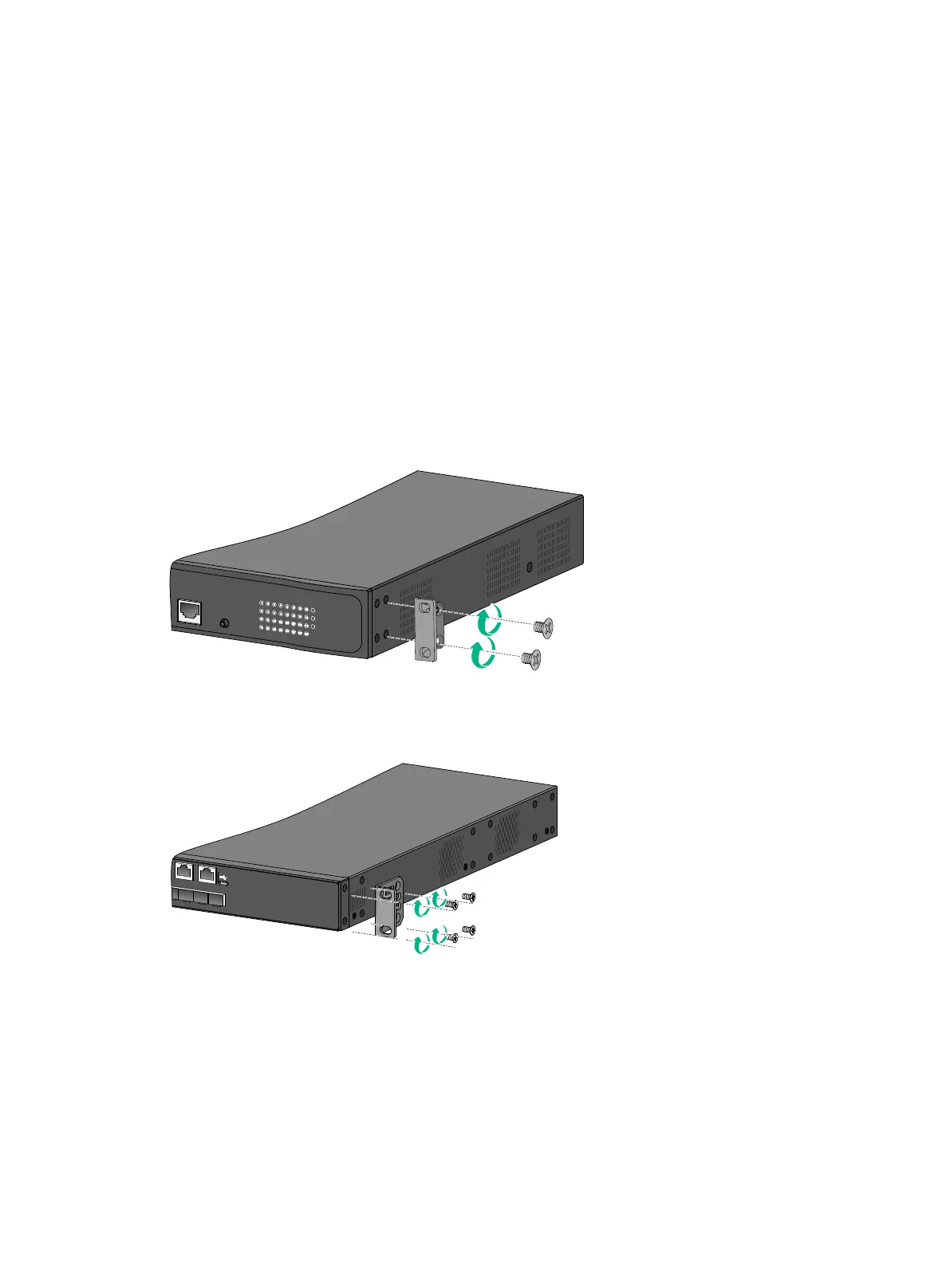
2. Align one mounting bracket with the screw holes at the mounting position. Use M4 screws to
attach the mounting bracket to the chassis. See Figure 3 for installing mounting bracket A,
Figure 4 and Figure 5 for installing mounting bracket B, and Figure 6 for installing mounting
bracket C.
M4 screws are provided only for switches shipped with mounting brackets.
An optional mounting bracket kit contains M4 screws.
3. Repeat step 2 to attach the other mounting bracket to the chassis.
Figure 3 Attaching mounting bracket A (HPE 5140 24G PoE+ 4SFP+ EI)
Figure 4 Attaching mounting bracket B to the port side mounting position (HPE 5140 24G
SFP w/8G Combo 4SFP+ EI)
 Loading...