12
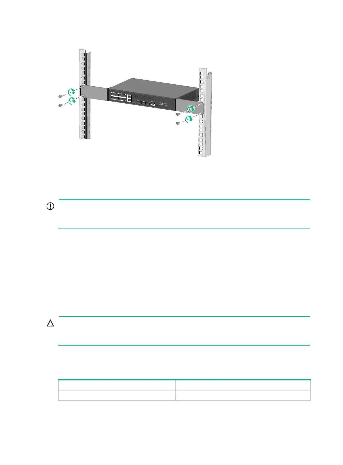
Figure 9 Mounting an HPE 5140 8G 2SFP 2GT Combo EI switch in the rack
Mounting the switch on a workbench
Ensure 10 cm (3.9 in) of clearance around the chassis for heat dissipation.
• Do not place heavy objects on the switch.
If a standard 19-inch rack is not available, you can place you switch on a workbench.
To mount the switch on a workbench:
1. Verify that the workbench is sturdy and reliably grounded.
2. Place the switch with bottom up, and clean the round holes in the chassis bottom with dry cloth.
3. Attach the rubber feet to the four round holes in the chassis bottom.
4. Place the switch with upside up on the workbench.
Mounting the switch on a wall
:
Before drilling holes in a wall, make sure no electrical lines exist in the wall.
• Leave a minimum clearance of 10 mm (0.39 in) around the chassis for heat dissipation.
Table 6 describes the switch models that support wall mounting and installation holes distances
required for wall-mounting the switch.
Table 6 Installation hole distances for switch models that support wall mounting
HPE 5140 8G 2SFP 2GT Combo EI 170 mm (6.69 in)
20 mm (0.79 in) long screws and screw anchors as shown in Figure 10 are provided with these
switches for wall-mounting.
 Loading...