32
As a best practice, use ring topology to connect the switches. The following describes cabling
schemes in ring topology.
Connecting the IRF member switches in one rack
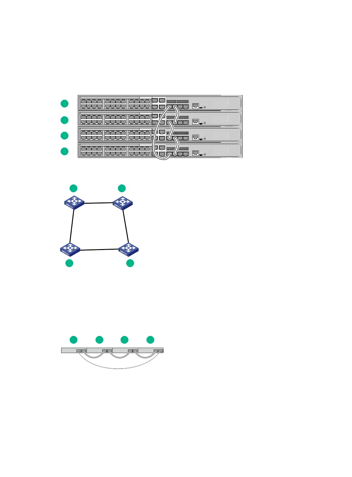
Use SFP cables to connect the IRF member switches in a rack as shown in Figure 35. The switches
in the ring topology (see Figure 36) are in the same order as connected in the rack.
Figure 35 Connecting the switches in one rack
Figure 36 IRF fabric topology
Connecting the IRF member switches in a ToR solution
You can install IRF member switches in different racks side by side to deploy a top of rack (ToR)
solution.
Figure 37 shows an example for connecting four top of rack IRF member switches by using SFP
transceiver modules and optical fibers. The topology is the same as Figure 36.
Figure 37 ToR cabling
Configuring basic IRF settings
After you install the IRF member switches, power on the switches, and log in to each IRF member
switch (see the fundamentals configuration guide for the switch series) to configure their member IDs,
member priorities, and IRF port bindings.
Follow these guidelines when you configure the switches:
 Loading...