15
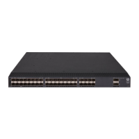
Figure 14 Attaching the grounding cable to the grounding hole of the switch (HPE 5140
24G PoE+ 4SFP+ EI)
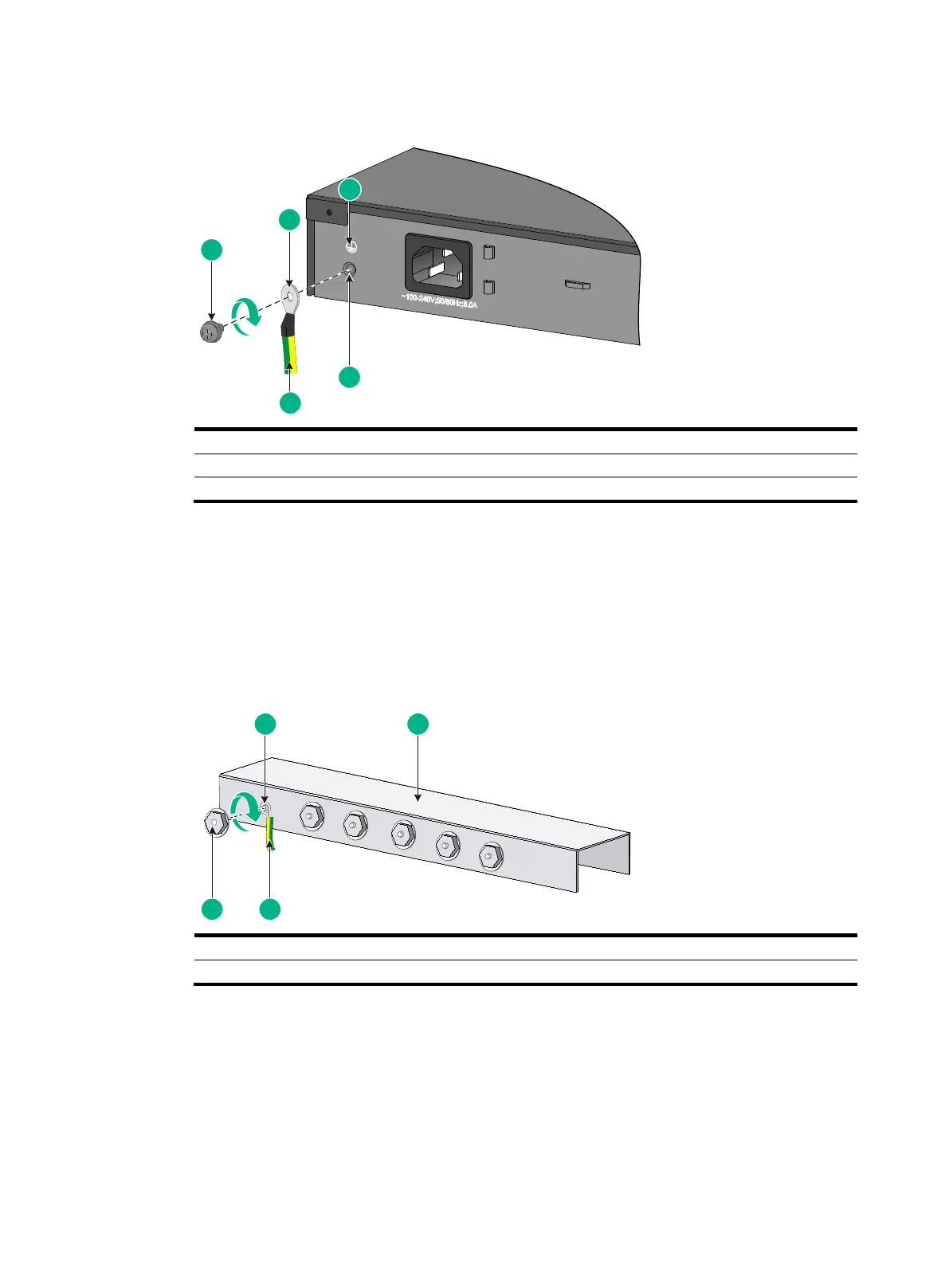
2. Connect the other end of the grounding cable to the grounding strip.
a. Cut the grounding cable to a length according to the distance between the switch and the
grounding strip.
b. Peel 20 mm (0.79 in) of insulation sheath by using a wire stripper.
c. Use the needle-nose pliers to bend the bare wire.
d. Hook the grounding cable to the post on the grounding strip, and use the hex nut to secure
the cable to the post.
Figure 15 Connecting the grounding cable to a grounding strip
Grounding the switch with a grounding conductor buried in
the earth ground
If the installation site has no grounding strips, but earth ground is available, hammer a 0.5 m (1.64 ft)
or longer angle iron or steel tube into the earth ground to serve as a grounding conductor.
The dimensions of the angle iron must be at least 50 × 50 × 5 mm (1.97 × 1.97 × 0.20 in). The steel
tube must be zinc-coated and its wall thickness must be at least 3.5 mm (0.14 in).
 Loading...