2-5
Installing the switch
Installation procedure
1. Prepare the installation site
Follow the installation guidelines to ensure proper operation of the switch in the
network:
■ Verify that all the cables meet the requirements of the “Cabling Specifications”
in Appendix A.
■ Protect the switch from radio frequency interference emissions.
■ Use electrical surge suppression.
■ Use safe connections. The cables, connectors, or shields must not be damaged.
Installation space requirements.
2. Mount the switch
HP PS1810-8G Switch
You can stack the HP PS1810-8G Switch with HP ProLiant MicroServers, mount it
on a wall, or on top of or under a horizontal surface.
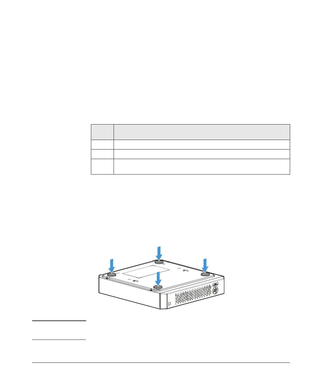
Before stacking it with HP servers or positioning the switch on a horizontal surface,
attach the rubber feet that are supplied in the accessory kit.
Note If you are mounting the switch on a wall or under a surface, do not attach the rubber
feet.
Switch
face
Clearance requirements
Front
At least 3 inches (7.6 cm) of space for the twisted-pair and fiber-optic cabling.
Back At least 1-1/2 inches (3.8 cm) of space for the power cord and switch cooling.
Sides
At least 3 inches (7.6 cm) for cooling, except if the switch is installed in an open
EIA/TIA rack.
 Loading...


