e.
Rear cover (see
Rear cover on page 53)
f.
Top cover (see
Top cover on page 55)
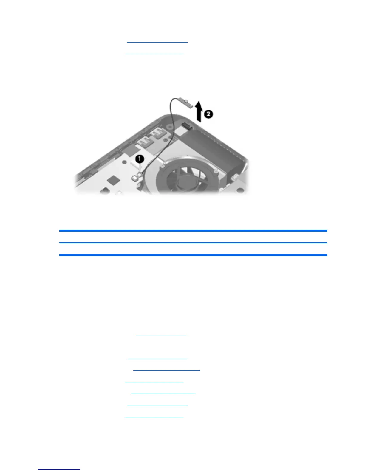
Remove the power connector LED board:
1. Disconnect the power connector LED board (1) from the system board.
2. Remove the power connector LED board (2).
Reverse this procedure to install the power connector LED board.
Rear USB board
Description Spare part number
Rear USB board (includes cable) 452315-001
Before removing the rear USB board, follow these steps:
1.
Shut down the computer. If you are unsure whether the computer is off or in Hibernation, turn the
computer on, and then shut it down through the operating system.
2.
Disconnect all external devices connected to the computer.
3.
Disconnect the power from the computer by first unplugging the power cord from the AC outlet and
then unplugging the AC adapter from the computer.
4.
Remove the battery (see
Battery on page 36).
5.
Remove the following components:
a.
Hard drive (see
Hard drive on page 42)
b.
Optical drive (see
Optical drive on page 49)
c.
Keyboard (see
Keyboard on page 50)
d.
Hinge cover (see
Hinge cover on page 52)
e.
Rear cover (see
Rear cover on page 53)
f.
Top cover (see
Top cover on page 55)
66 Chapter 4 Removal and replacement procedures
 Loading...