Component identification 12
Item Description
23 Power supply connector 2
24 PCI power connector
25 TPM connector
26 PCIe riser board connectors (2)
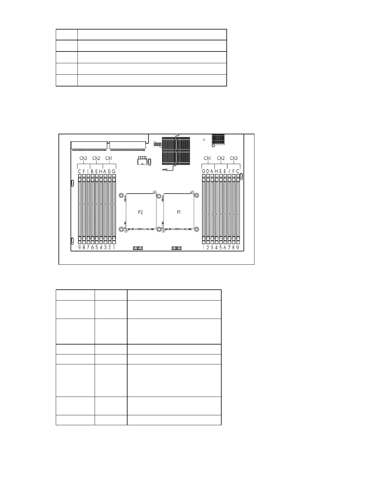
DIMM slots
DIMM slots are numbered sequentially (1 through 9) for each processor. The supported AMP modes use
the letter assignments for population guidelines.
System maintenance switch
Position Default Function
S1 Off Off = iLO 3 security is enabled.
On = iLO 3 security is disabled.
S2 Off
Off = System configuration can be
changed.
On = System configuration is locked.
S3 Off Reserved
S4 Off Reserved
S5 Off
Off = Power-on password is
enabled.
On = Power-on password is
disabled.
S6 Off Off = No function
On = Clear NVRAM
S7 — Reserved
 Loading...