3-2 Powermax105 Operator Manual
Controls and indicators
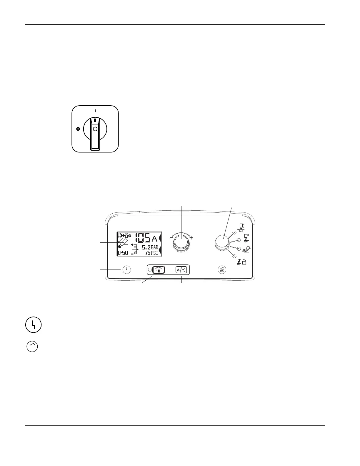
Powermax105 power supplies have the following: ON/OFF switch, adjustment knob, automatic/manual pressure setting
mode selector, current/gas selector, operating mode switch, indicator LEDs, and a status screen. These controls and
indicators are described on the following pages.
Rear controls
ON (I)/OFF (O) power switch
Activates the power supply and its control circuits.
Front controls and LEDs
Fault LED (yellow)
Power ON LED
(green)
Status screen
Automatic/manual pressure
setting mode selector
Current/gas
selector
Operating
modeswitch
Modes described
onnext page
Adjustment knob
Fault LED (yellow)
When illuminated, this LED indicates that there is a fault with the power supply.
AC
Power ON LED (green)
When illuminated, this LED indicates that the power switch has been set to I (ON) and that the safety
interlocks are satisfied. When blinking, the power supply has a fault.

 Loading...


