EasyManuals Logo
Home>Hypertherm>Welding System>Powermax30 XP

Hypertherm Powermax30 XP Service Manual

Hypertherm Powermax30 XP
201 pages
To Next Page IconTo Next Page
To Previous Page IconTo Previous Page
Page #135 background imageLoading...
Page #135 background image
Powermax30 XP Service Manual 808150 Revision 0 135
6 Power Supply Component Replacement
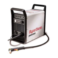
4. Remove the connector at J12 by pressing up on the tab in the connection slot with a small blade screwdriver and
then pulling the connector out toward the power supply’s front panel.
Figure 69
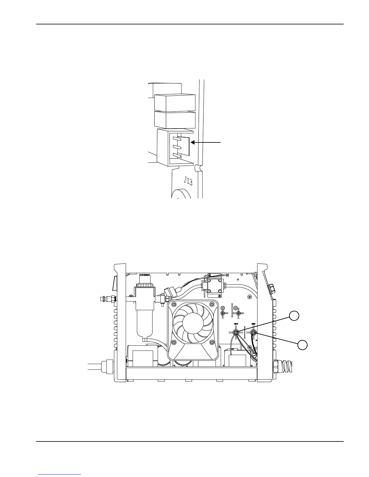
5. Locate the studs that attach the white wire group and the red wire from the torch lead to the power supply’s center
panel (on the fan side of the power supply).
6. Use an 8 mm (5/16 inch) nut driver to remove the nuts from the studs, and slide the ring terminals off the studs.
Figure 70
Push tab toward connector
1
2
1
Red wire
2
White wire group

Table of Contents

Other manuals for Hypertherm Powermax30 XP

Questions and Answers:

Question and Answer IconNeed help?

Do you have a question about the Hypertherm Powermax30 XP and is the answer not in the manual?

Hypertherm Powermax30 XP Specifications

General IconGeneral
BrandHypertherm
ModelPowermax30 XP
CategoryWelding System
LanguageEnglish

Related product manuals