• Check that the OK LED (back of enclosure) is off.
Stopping I/O
During troubleshooting disk drive and connectivity faults, stop I/O to the affected declustered array from
all hosts as a data protection precaution.
Removing an IOM/EBOD expander module
Important: Considerations for removing IOMs/EBOD expander modules:
• In a dual-controller environment, you may hot-swap a single controller module in an operational
enclosure, provided you rst shut down the faulty controller.
• In a dual-controller environment—if replacing both controller modules—you must adhere to the
instructions provided in Before you begin
and perform an orderly shutdown of the enclosure.
• Do not remove a faulty module unless its replacement is on-hand. All CRU modules must be in place
when the system is in operation.
See CAUTION bullets regarding electrostatic discharge and anti-static protection.
Illustrations in the IOM/EBOD expander module replacement procedures show rear panel views of the
enclosure, and IOMs/EBOD expander modules are properly aligned for insertion into the rear panel of the
enclosure.
1. Locate the enclosure whose ID LED (enclosure front panel – left side) is illuminated, and within the
enclosure, locate the IOM/EBOD expander module to be replaced.
2. Disconnect any cables connected to the IOM/EBOD expander module.
Label each cable to facilitate re-connection to the replacement IOM/EBOD expander module.
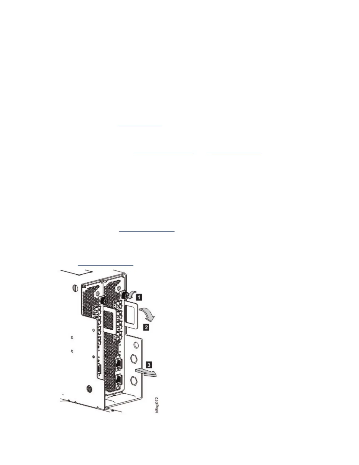
3. Unlock the IOM/EBOD expander module latch handle by turning the thumbscrew counter-clockwise as
shown in detail No.1 in Figure 74 on page 79.
Take care not to remove the thumbscrew from the IOM/EBOD expander module latch handle.
4. Grasp the IOM latch handle between the thumb and index nger and pull. Revolve the handle out and
downward to lever the IOM/EBOD expander module out of the enclosure as shown in details No.2 and
No.3 in Figure 74 on page 79.
Figure 74. Removing an IOM/EBOD expander module (1 of 2)
Chapter 7. Module removal and replacement
79
 Loading...