Adding and removing drives 7-7
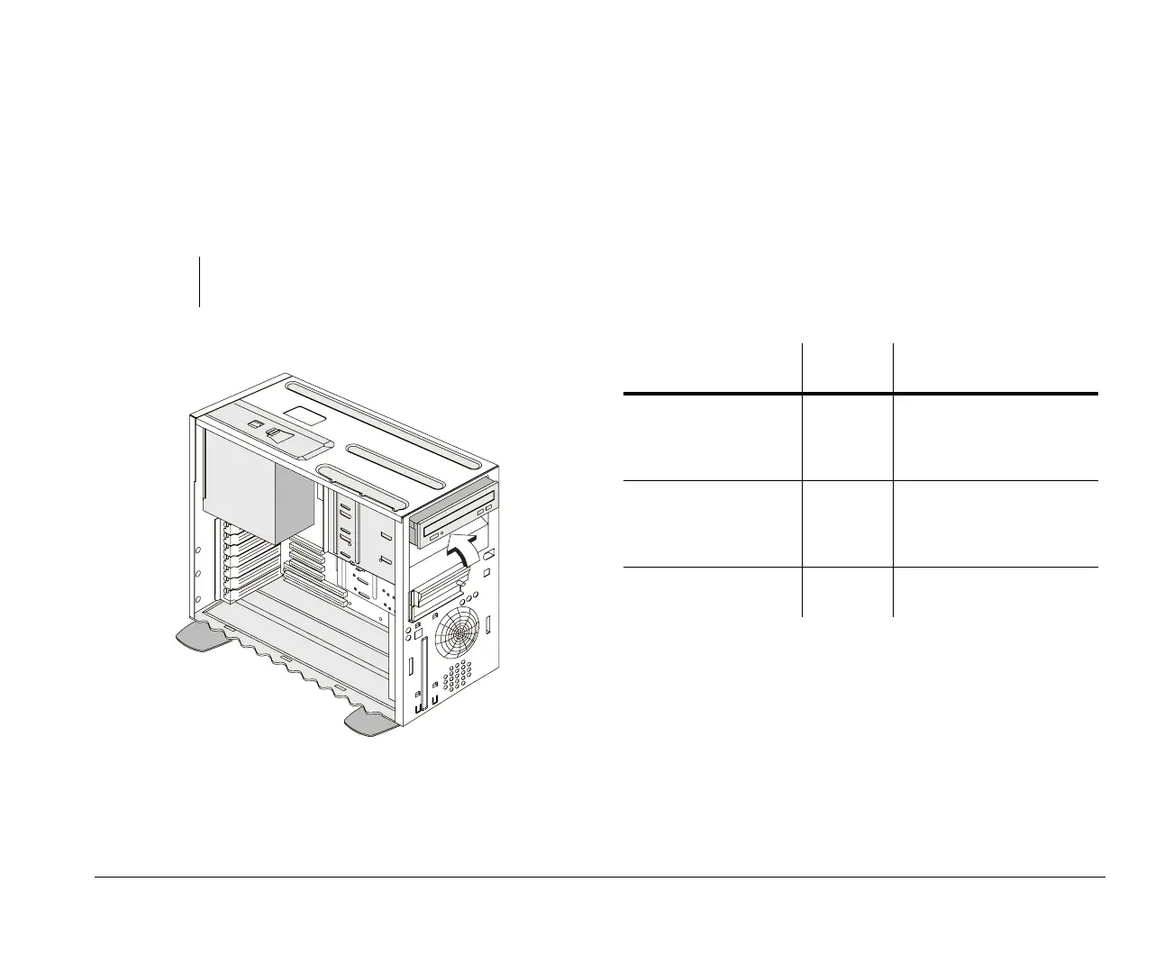
Pushing back the metal
bay covers
After removing the system unit cover, you will see that the
empty drive bays on the system unit internal frame still have
metal covers. Push back these metal covers to a 90-degree
angle before you install disk drives.
Identifying signal cable
connectors
When you install a drive of any type, you must attach the
signal cable (also called the data cable) from the drive to a
connector on the system board. The following table identifies
each connector on the system board and the type of drive
that uses the connection. Note that the first two connectors
are for IDE/ATA PCI bus drives (such as hard disk drives and
CD-ROM drives), while the third connector is for diskette
interface drives (such as diskette drives or tape drives).
Caution:
Take extra care when pushing back the metal covers to
avoid hurting yourself.
System board
connector
Interfac
e type
Type of drive using the
connector
Primary IDE –
CN9
IDE/ATA
PCI bus
Preferred location for first
and second hard disk drives.
A CD-ROM drive can also
be attached here.
Secondary IDE –
CN8
IDE/ATA
PCI bus
Preferred location for a CD-
ROM drive. An additional
hard disk drive could be
attached here.
Diskette –
CN19
Standard
diskette
Should be used for diskette
drives or tape drives.
v65xahb.book : chap-7.fm Page 7 Friday, January 16, 1998 4:27 PM
 Loading...


