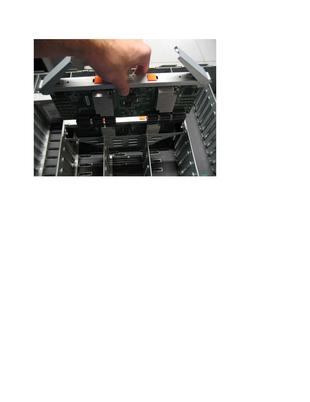
5. Press the secondary expander module down into position in the enclosure.
6. Rotate the handles on the secondary expander module to the closed position
to lock it in the enclosure.
7. If needed, repeat step 3 on page 79 through step 6 to replace the other
secondary expander module.
8. Replace the top cover, as described in “Installing or replacing the top cover:
2077-92F” on page 71.
9. If needed, reconnect the power cables to the expansion enclosure, as described
in “Powering on the expansion enclosure: 2077-92F” on page 131.
10. Check the LEDs on the top of the secondary expander module to verify that it
is receiving power.
“Storwize V5000 Gen2 2077-92F expansion enclosure LEDs and indicators” on
page 135 describes the status indicated by the LEDs.
Installing or replacing the fascia: 2077-92F
During the initial installation process or after you perform service, you can install
the fascia components on the front of a 2077-92F expansion enclosure.
About this task
The 4U fascia covers the display panel of the expansion enclosure. It is attached to
the enclosure by four screws. The bottom 1U fascia covers both of the power
supply units (PSUs) on the enclosure. As Figure 68 on page 81 shows, the fascias
are independent; you can remove or replace one without having to remove or
replace the other.
Figure 67. Replace the secondary expander module
80 Storwize V5000 Gen2: Quick Installation Guide
 Loading...


