Figures
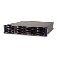
1. Isometric view of the DCS3700 ......7
2. DCS3700 hot-swap drive drawers .....8
3. DCS3700 drive drawer .........8
4. Location of the DCS3700 controllers .....9
5. DCS3700 connectors..........10
6. Cache battery and memory cache DIMM
locations .............11
7. ESM SAS port locations........12
8. Location of seven-segment numeric display on
ESM...............13
9. Power supply components .......13
10. Fan assembly components .......14
11. Storage expansion enclosure airflow ....14
12. SFP module and fibre optic cable .....15
13. DCS3700 airflow ...........19
14. Example of cold aisle/hot aisle rack
configuration ............22
15. Front rack mounting template ......31
16. Rear rack mounting template ......32
17. DCS3700 drive drawer with labeled disk
drives ..............38
18. Dual-controller DS3700 storage subsystem
ports and controllers (with an optional SAS
host port adapter) ..........41
19. Dual-controller DS3700 storage subsystem
ports and controllers (with an optional Fibre
Channel host port adapter) .......42
20. Mini-SAS cable ...........43
21. Connecting a mini-SAS cable.......43
22. Removing a mini-SAS cable .......44
23. SFP module and protective cap ......45
24. Installing an SFP module into the host port 46
25. Unlocking the SFP module latch - plastic
variety ..............46
26. Unlocking the SFP module latch - wire variety 47
27. Recommended bending and looping
specifications for fibre-optic cables .....48
28. LC-LC Fibre Channel cable .......48
29. Removing fibre-optic cable protective caps 49
30. Inserting an LC-LC Fibre Channel cable into
an SFP module ...........50
31. LC-LC Fibre Channel cable lever and latches 50
32. Removing the LC-LC Fibre Channel cable 51
33. ESM connectors ...........51
34. Single Expansion Enclosures .......53
35. Dual Expansion Enclosures .......54
36. Host-agent (in-band) management .....56
37. Direct (out-of-band) management method 57
38. Dual-controller direct-attached Fibre Channel
connection to two HBAs in the same host
(redundant host connection) .......58
39. Dual-controller direct-attached Fibre Channel
connections to multiple HBAs in multiple
hosts ...............59
40. Example of DCS3700 connected to a single
BladeCenter unit ...........60
41. Dual-controller direct-attached Fibre Channel
connection to two HBAs in the same host
(redundant host connection) .......62
42. Dual-controller direct-attached Fibre Channel
connections to multiple HBAs in multiple
hosts ...............62
43. Example of a single Fibre Channel SAN fabric
configuration ............63
44. Example of a dual Fibre Channel SAN fabric
configuration ............64
45. Example of two storage subsystems in a dual
Fibre Channel SAN environment .....64
46. Example of a multiple-host, multiple-port, and
multiple-fabric (Fibre Channel and SAS)
configuration ............65
47. Power-supply switches and connectors for
DS3500 dc models ..........69
48. DCS3700 front LEDs and controls .....73
49. DS3524 storage subsystem and EXP3524
storage enclosure front LEDs.......73
50. Controller LEDs ...........74
51. Fibre Channel host port adapter LEDs . . . 75
52. SAS host port adapter LEDs .......75
53. ESM LEDs .............76
54. Fan assembly LEDs ..........77
55. AC power-supply LEDs ........77
56. Drive drawer LEDs ..........78
57. Disk drive LEDs ...........79
58. Numeric display LEDs .........80
59. Removing a controller .........90
60. Removing the cover..........91
61. Removing and replacing a controller ....93
62. Removing the battery unit from the controller 93
63. Cache backup flash memory device location 94
64. Removing a controller .........97
65. Removing the host port adapter filler panel 98
66. Installing a host port adapter ......98
67. Remove controller from the chassis ....99
68. Opening the drive drawer .......102
69. Raising the drive handle ........102
70. Aligning the drive ..........102
71. Locking the drive in place .......103
72. Replacing a power supply .......112
73. Removing a controller.........114
74. Removing a battery unit from the controller 114
75. Memory cache DIMM location ......115
76. Removing a controller.........116
77. Removing the DIMM from the controller 116
78. Installing the DIMM in the controller 117
79. Cache backup flash memory device ....118
80. Removing the bezel .........119
81. Removing an environmental service module 120
82. Removing a fan assembly .......121
83. Rear view of the storage expansion enclosure
with the right fan assembly removed . . . 123
© Copyright IBM Corp. 2011 vii
 Loading...


