Attention:
1. Repeatedly turning the power off and on without waiting for the drives to spin down can damage
the drives. Always wait at least 90 seconds after you turn off the power before you turn it on again.
2. If you are connecting a power cord to a storage subsystem enclosure, turn off the power switches
first. If the main circuit breaker is off, make sure that both power switches are off on each storage
enclosure in the rack before you turn on the main circuit breakers.
3. Turn on the power to the supporting devices (for example, Ethernet switches and management
stations) before powering on the storage subsystem enclosures.
1. Are the main circuit breakers turned on?
– Yes: Turn off both power switches on each enclosure that you intend to connect to the power.
– No: Turn off both power switches on all enclosures in the storage subsystem.
2. Make sure that all power cords are connected.
Note: If the power cords are not connected, turn off both power switches on all modules in the
configuration before you connect power cords or turn on the main circuit breakers.
3. If the main circuit breakers are turned off, turn them on.
Attention: You must turn on power to each attached expansion enclosure before you turn on
power to the storage system so that the controllers recognize all drives in the configuration during
the startup process.
4. Depending on the number of storage enclosures in the configuration, the storage subsystem might
take up to 10 minutes to fully power-on. While each storage enclosure powers-on, the green and
amber LEDs on the front and rear of the storage enclosure turn on and off intermittently. The cache
battery backup self-test might take up to an additional 15 minutes to be completed. During this
time, the LEDs on the front and rear of the storage subsystem might flash intermittently.
Check the LEDs on the front and rear of all the storage enclosures. Make sure that no amber LEDs
are lit on any of the storage enclosures.
5. Determine the status of all the components in the storage subsystem configuration by completing
the following steps:
a. Check all LEDs on each component in the DCS3700 expansion enclosures. Make sure that all the
LEDs show normal status. For more information about LED status for expansion enclosures, see
“Checking the LEDs” on page 73.
b. Check all LEDs on each component in the DCS3700 storage system. Make sure that all the LEDs
show normal status. For information about LED status, see “Checking the LEDs” on page 73 or
“Solving problems” on page 129.
dcsi0004
1
2
Lnk Lnk Lnk Lnk
ID/Diag
Lnk Lnk
8 8
1
2
Lnk Lnk Lnk Lnk
ID/Diag
Lnk Lnk
8 8
ACDC
2
1
I
O
ACDC
2
1
I
O
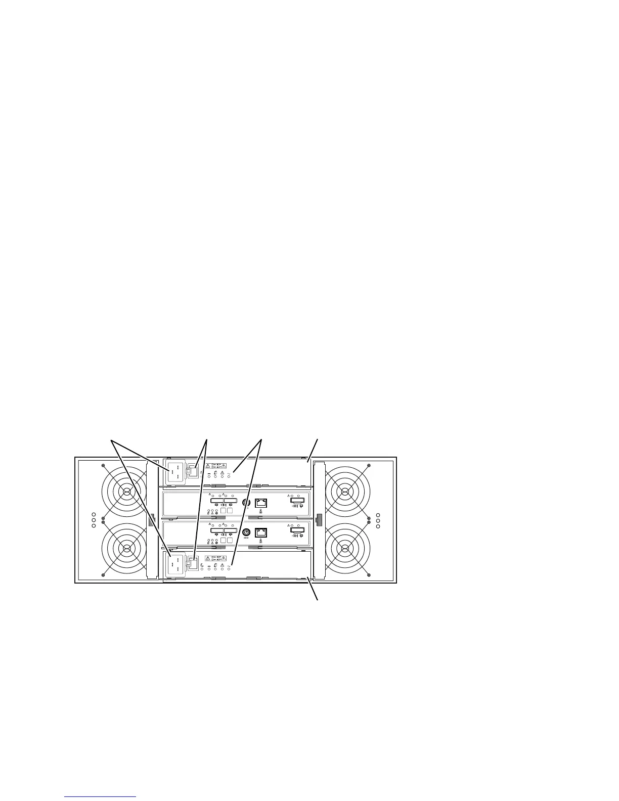
Power connector
Power supply A
Power switch LEDs
Power supply B
Figure 47. Power-supply switches and connectors for DS3500 dc models
Chapter 4. Operating the DCS3700 storage system and expansion enclosure 69
 Loading...


