Table 2. System board jumpers (continued)
Jumper number Jumper name Jumper setting
J2 UEFI boot recovery jumper
v Pins 1 and 2: Normal
(default) Loads the
primary server firmware
ROM page.
v Pins 2 and 3: Loads the
secondary (backup) server
firmware ROM page.
Note:
1. If no jumper is present, the server responds as if the pins are set to 1 and 2.
2. Changing the position of the UEFI boot recovery jumper from pins 1 and 2 to pins 2
and 3 before the server is turned on alters which flash ROM page is loaded. Do not
change the jumper pin position after the server is turned on. This can cause an
unpredictable problem.
Important:
1. Before you change any switch settings or move any jumpers, turn off the
server; then, disconnect all power cords and external cables. Review the
information in Safety, “Installation guidelines” on page 30, “Handling
static-sensitive devices” on page 32, and “Turning off the server” on page 21.
2. Any system-board switch or jumper blocks that are not shown in the
illustrations in this document are reserved.
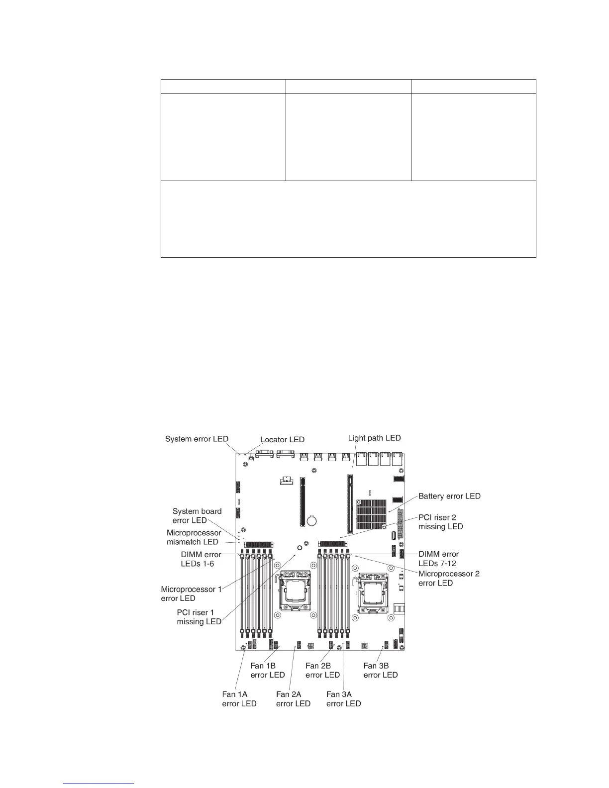
System-board LEDs
The following illustration shows the light-emitting diodes (LEDs) on the system
board.
28 System x3530 M4 Type 7160: Installation and Service Guide
 Loading...