3. Insert the hard disk drive backplate into the slots on the backplate bracket and
push the hard disk drive backplate assembly down until the backplate is seated
firmly.
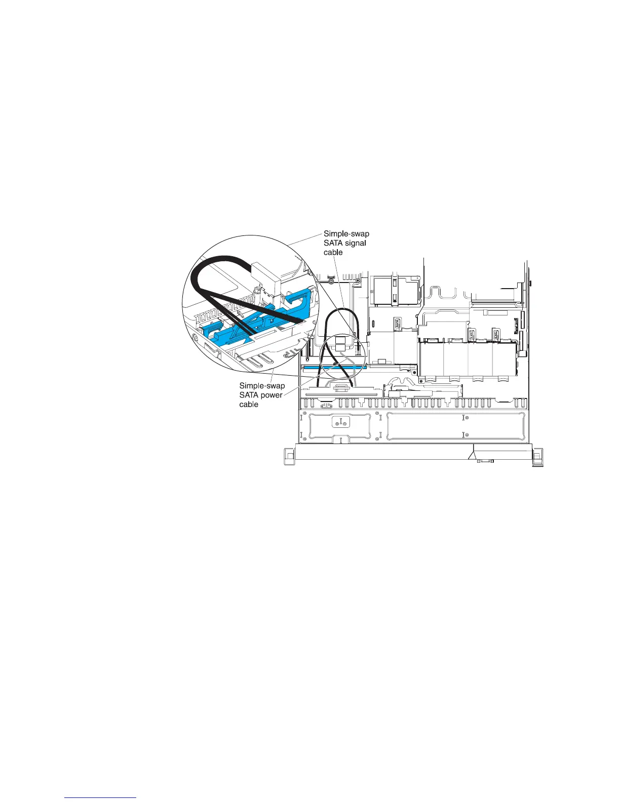
4. Connect the power and signal cables to the system board. Route the power
cable from the drive backplate through the hole on the right of the blue adapter
retention bracket and connect it to the Simple-swap SATA power connector
(see “System-board internal connectors” on page 16); then, route the signal
cable from the drive backplate over the blue adapter retention bracket and
connect it to the Simple-swap SATA signal connector, as shown in the
following illustration.
5. Reinstall the hard disk drives and filler panels.
6. Install the cover (see “Installing the cover” on page 174).
7. Slide the server into the rack.
8. Reconnect the power cords and any cables that you removed.
9. Turn on the peripheral devices and the server.
Removing the operator information panel assembly
To remove the operator information panel, complete the following steps.
1. Read the safety information that begins on page vii and “Installation guidelines”
on page 167.
2. Turn off the server and peripheral devices and disconnect all power cords; then,
remove the cover (see “Removing the cover” on page 174).
3. Disconnect the cable from the back of the operator information panel assembly.
4. Use an object to push down on the release tab; hold down the release tab and
push the blue push point on the rear of the panel to the front of the server.
240 IBM System x3550 M3 Types 4254 and 7944: Problem Determination and Service Guide
 Loading...


