is removed.
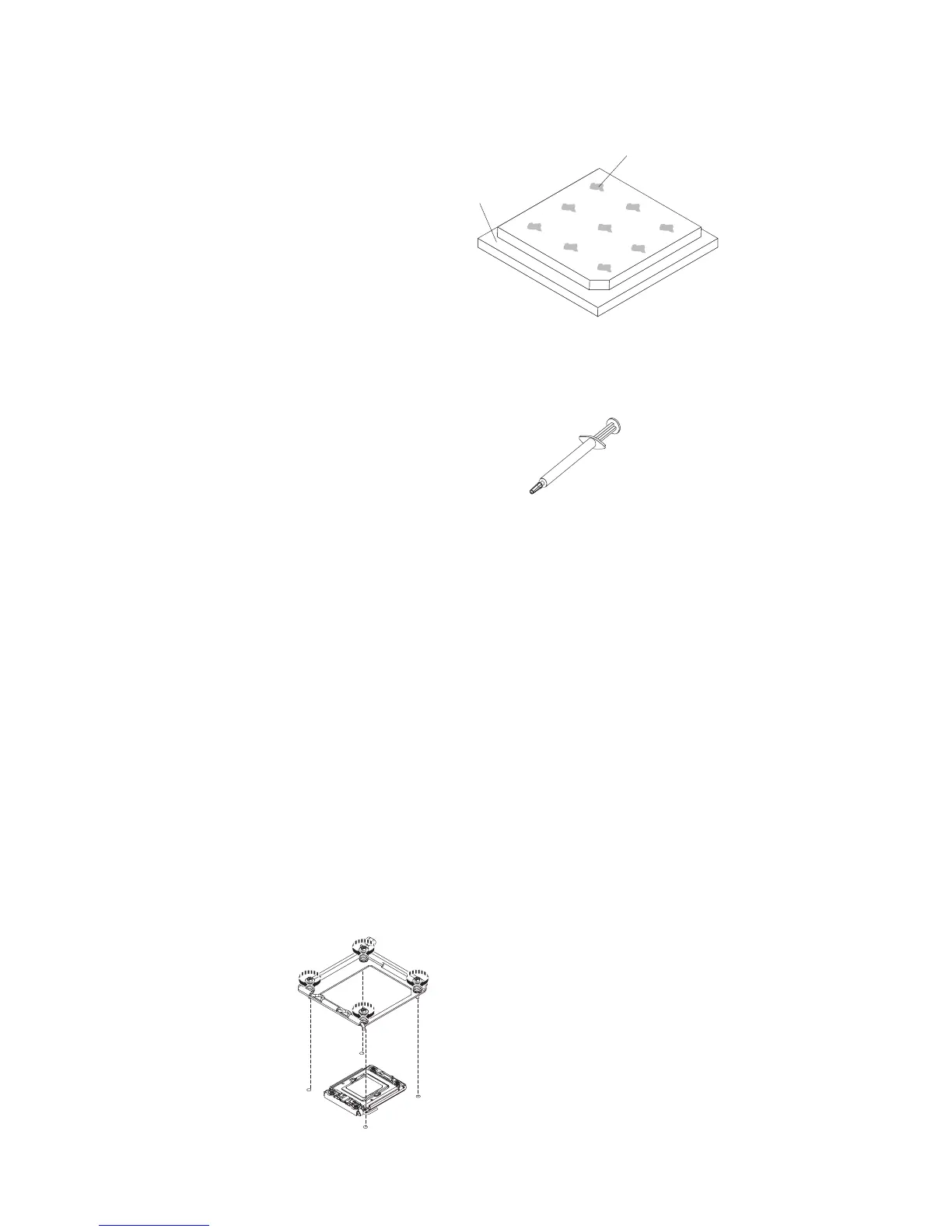
Microprocessor
0.02 mL of thermal
grease
5. Use the thermal-grease syringe to place 9 uniformly spaced dots of 0.02 mL
each on the top of the microprocessor. The outermost dots must be within
approximately 5 mm of the edge of the microprocessor; this is to ensure uniform
distribution of the grease.
Note: If the grease is properly applied, approximately half of the grease will
remain in the syringe.
6. Install the heat sink onto the microprocessor as described in “Installing a
microprocessor and heat sink” on page 245.
Removing the heat sink retention module
To remove a heat sink retention module, complete the following steps:
1. Read the safety information that begins on page vii and “Installation guidelines”
on page 167.
2. Turn off the server and any attached devices.
3. Turn off the peripheral devices and disconnect all power cords; then, remove
the cover (see “Removing the cover” on page 174).
4. Remove the applicable air baffle.
5. Remove the microprocessor and heat sink (see “Removing the microprocessor
2 air baffle” on page 175).
Attention: When you remove a microprocessor and heat sink, be sure to
keep each heat sink with its microprocessor for reinstallation.
6. Use a screwdriver and remove the four screws that secure the retention module
to the system board; then, lift the retention module from the system board.
Chapter 5. Removing and replacing server components 249
 Loading...


