v Video connector: Connect a monitor to this connector. The video connectors on
the front and rear of the server can be used simultaneously.
v USB connectors: Connect a USB device, such as a USB mouse or keyboard to
any of these connectors.
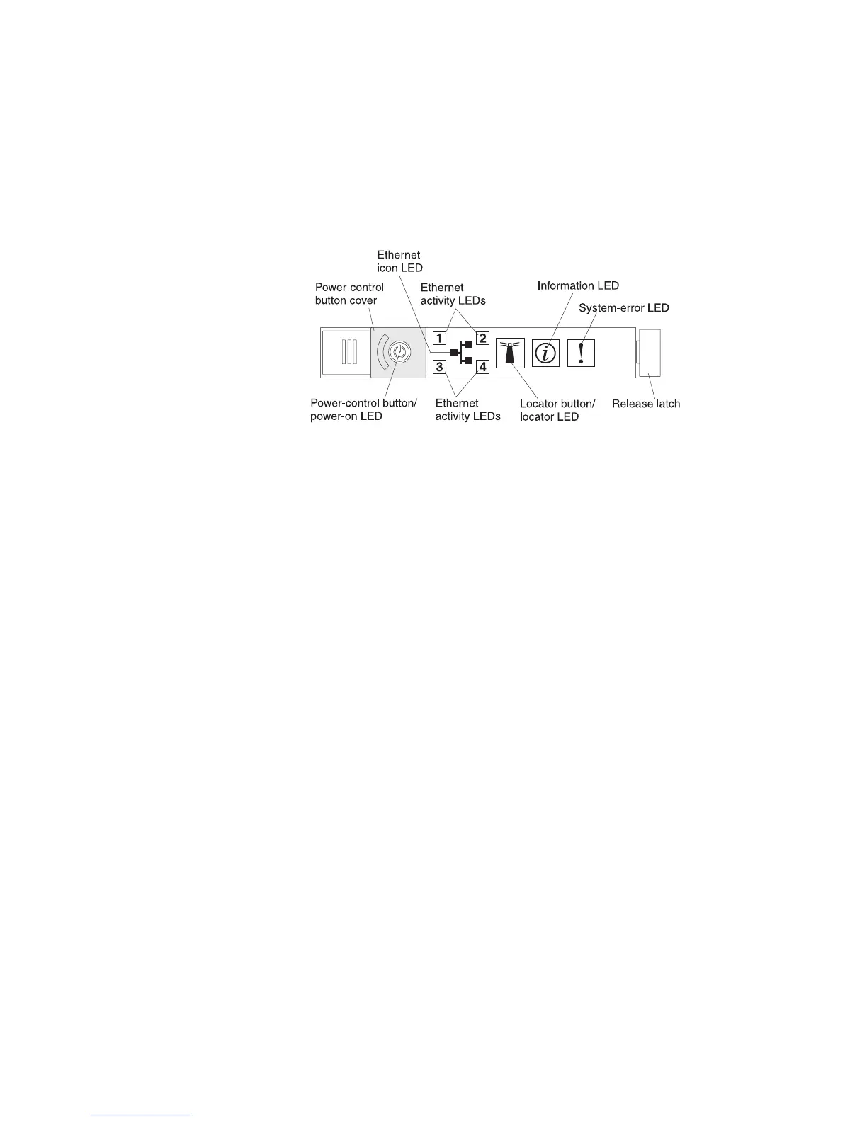
Operator information panel
The following illustration shows the controls and LEDs on the operator information
panel.
v Power-control button and power-on LED: Press this button to turn the server
on and off manually or to wake the server from a reduced-power state. The
states of the power-on LED are as follows:
Off: AC power is not present, or the power supply or the LED itself has failed.
Flashing rapidly (4 times per second): The server is turned off and is not
ready to be turned on. The power-control button is disabled. This will last
approximately 20 to 40 seconds.
Flashing slowly (once per second): The server is turned off and is ready to
be turned on. You can press the power-control button to turn on the server.
Lit: The server is turned on.
Fading on and off: The server is in a reduced-power state. To wake the
server, press the power-control button or use the IMM Web interface. See
“Logging on to the Web interface” on page 268 for information on logging on
to the IMM Web interface.
v Ethernet activity LEDs: When any of these LEDs is lit, they indicate that the
server is transmitting to or receiving signals from the Ethernet LAN that is
connected to the Ethernet port that corresponds to that LED.
v System-locator button/LED: Use this blue LED to visually locate the server
among other servers. This LED is also used as a presence detection button. You
can use IBM Systems Director to light this LED remotely. This LED is controlled
by the IMM. When you press the System-locator button, the LED will blink and it
will continue to blink until you press it again to turn it off. The locator button is
pressed to visually locate the server among the others servers. It is also used as
the physical presence for the Trusted Platform Module (TPM).
v System-information LED: When this amber LED is lit, it indicates that a
noncritical event has occurred. Check the error log for additional information. See
“Error logs” on page 25 for information about the error logs.
v System-error LED: When this amber LED is lit, it indicates that a system error
has occurred. A system-error LED is also on the rear of the server. An LED on
the light path diagnostics panel on the operator information panel is also lit to
help isolate the error. This LED is controlled by the IMM.
v Hard drive activity LED: When this green LED is lit, it indicates that one of the
hard disk drives is in use.
10 IBM System x3550 M3 Types 4254 and 7944: Problem Determination and Service Guide
 Loading...


