Chapter 5. IBM BladeCenter HX5 187
Attachment to a single HX5 using the IBM HX5 MAX5 1-node Scalability kit, part number
59Y5877, as described in 5.8.3, “HX5 with MAX5” on page 190
Communication with the processors on the HX5 using high-speed QPI links
MAX5 is standard with certain models, as listed in 5.4, “Models” on page 183. For other
models, MAX5 is available as an option, as listed in Table 5-8.
Table 5-8 IBM MAX5 for BladeCenter
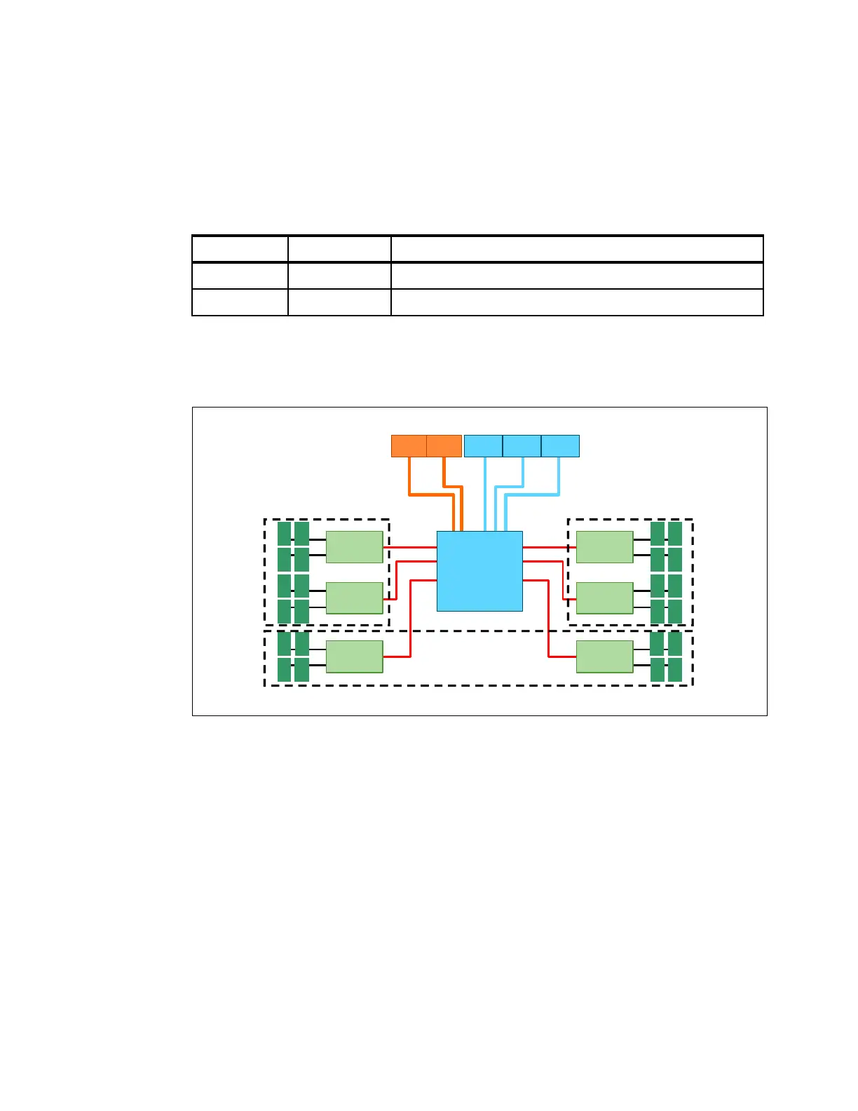
MAX5 consists of the EX5 node controller chip, six memory buffers, and 24 DIMM sockets.
The MAX5 has three power domains: A, B, and C. Each power domain includes two memory
controllers and eight DIMM sockets. Figure 5-7 shows the layout of the MAX5.
Figure 5-7 MAX5 memory expansion blade
In the next section, 5.8, “Scalability” on page 188, we describe how the MAX5 connects to the
HX5. We explain the memory options and rules in 5.10, “Memory” on page 194.
Part number Feature code Description
46M6973 1740 IBM MAX5 for BladeCenter
59Y5877 1742 IBM HX5 MAX5 1-node Scalability kit
Logical connectors to HX5 blades
SMI
links
12
34
Memory
buffer
56
78
Memory
buffer
109
1112
Memory
buffer
QPIQPI EXA EXAEXA
14 13
16 15
Memory
buffer
20 19
18 17
Memory
buffer
23 24
21 22
Memory
buffer
IBM EXA
chip
Power domain A Power domain B
Power domain C
 Loading...


