Chapter 7. IBM System x3690 X5 315
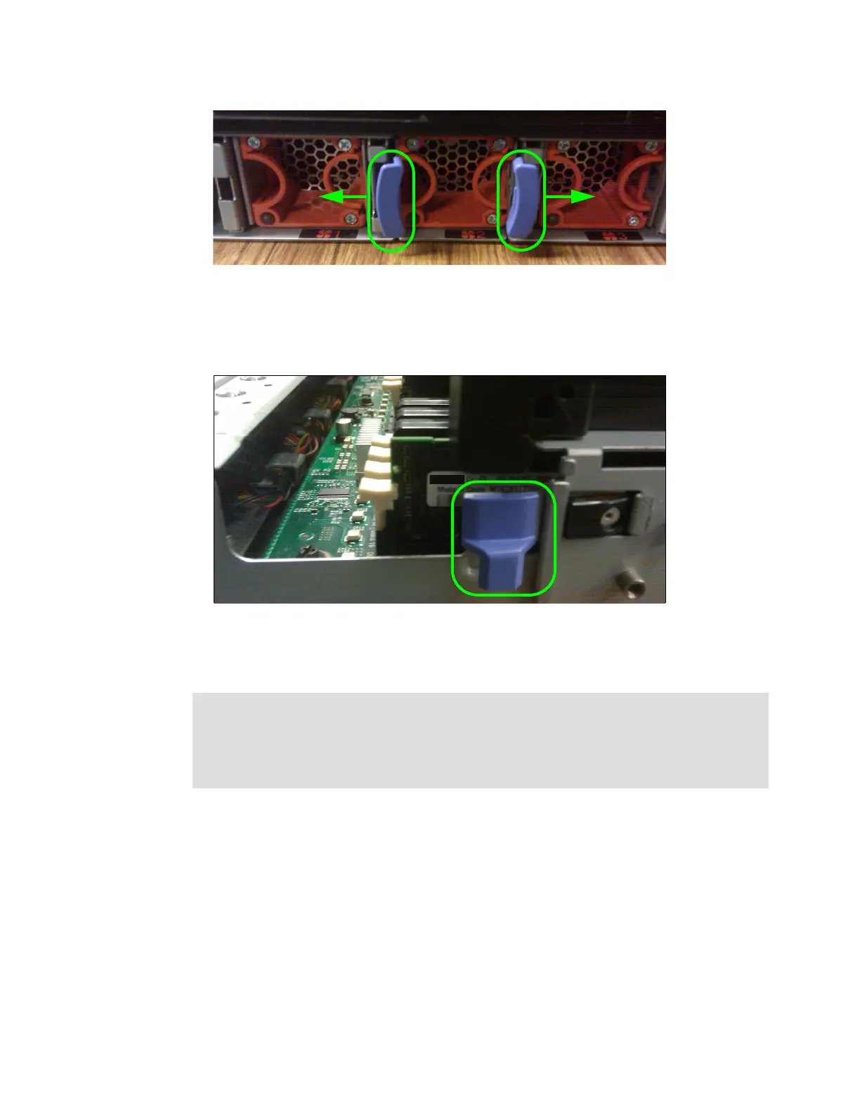
Figure 7-12 Blue release tabs for the memory tray cam levers
4. You can then pull the memory tray out about 30% before it stops. This design allows you to
get a better grip on the tray on either side and then use your fingers to push in another set
of blue release tabs on either side of the tray, as shown in Figure 7-13.
Figure 7-13 Final release tab for removing the MAX5 memory tray
5. Slide the memory tray completely out and place it on a flat work surface to work on the
memory.
For the memory population order, see 4.8, “Memory” on page 131.
After the MAX5 is installed and configured properly, you can confirm a successful link
between the server and the MAX5 when both units power on and off as one complete unit
and the memory in the MAX5 can be seen by the server. You will also see the following
message during POST:
“System initializing memory with MAX5 memory scaling”
Power: You must remove the ac power from both the server and the attached MAX5 before
removing the memory tray. The FPGAs of both the server and the MAX5 are still active
components when the server is powered down but not removed from utility power. FPGA
components exist on both the server and the MAX5. Removing the memory board with ac
power still active damages the FPGA components of both the server and the MAX5.
 Loading...


