5. Move the UEFI boot backup jumper from pins 1 and 2 to pins 2 and 3 to
enable the UEFI recovery mode.
6. Reinstall the server cover; then, reconnect all power cords.
7. Restart the server. The system begins the power-on self-test (POST).
8. Boot the server to an operating system that is supported by the firmware
update package that you downloaded.
9. Perform the firmware update by following the instructions that are in the
firmware update package readme file.
10. Turn off the server and disconnect all power cords and external cables, and
then remove the side cover (see “Removing the side cover” on page 38).
11. Move the UEFI boot backup jumper from pins 2 and 3 back to the primary
position (pins 1 and 2).
12. Reinstall the cover (see “Replacing the side cover” on page 182).
13. Reconnect the power cord and any cables that you removed.
14. Restart the server. The system begins the power-on self-test (POST). If this
does not recover the primary bank, continue with the following steps.
15. Remove the side cover (see “Removing the side cover” on page 38).
16. Reset the CMOS by removing the system battery (see “Removing the system
battery” on page 279).
17. Leave the system battery out of the server for approximately 5 to 15 minutes.
18. Reinstall the system battery (see “Replacing the system battery” on page 281).
19. Reinstall the cover (see “Replacing the side cover” on page 182).
20. Reconnect the power cord and any cables that you removed.
21. Restart the server. The system begins the power-on self-test (POST).
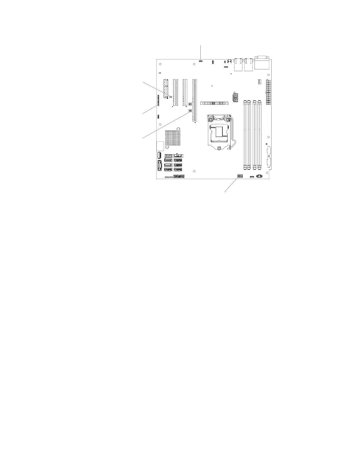
Low security jumper (J12)
IMM SPI enable
jumper (OVR 1)
UEFI boot backup
jumper (J16)
Clear CMOS jumper
(CLR RTC 1)
System TPM physical
jumper (SW1)
Figure 75. Location of the switches, jumpers, and buttons on the system board
162 System x3100 M5 Type 5457: Installation and Service Guide
 Loading...