6. Install the hard disk drive fan duct onto the hard disk drive cage (see
“Replacing the hard disk drive fan duct” on page 225).
7. Stand the server back up in its vertical position.
8. Install the hot-swap hard disk drives that you removed from the hard disk
drive cage (see “Replacing a hot-swap hard disk drive” on page 220).
9. Install the lower bezel (see “Replacing the lower bezel” on page 190).
10. Install and lock the side cover (see “Replacing the side cover” on page 182).
11. Reconnect the external cables and power cords; then, turn on the attached
devices and turn on the server.
Removing the operator information panel assembly
Use this information to remove the operator information panel assembly
To remove the operator information panel assembly on 4U server models with
non-hot-swap power supplies, complete the following steps. For the 5U server
model with hot-swap power supplies, please see the next sub-section.
1. Read the safety information in “Safety” on page vii and “Installation
guidelines” on page 35.
2. Turn off the server and all peripheral devices; then, disconnect the power
cords and all external cables.
3. Remove the bezel (see “Removing the bezel” on page 40).
4. Carefully turn the server on its side so that it is lying flat, with the cover
facing up.
Attention: Do not allow the server to fall over.
5. Remove the side cover (see “Removing the side cover” on page 38).
6. Remove the air baffle (see “Removing the air baffle” on page 39).
7. Disconnect the operator information panel assembly cable from the system
board, and note the routing of the cable (see “System-board internal
connectors” on page 30 for the location of the operator information panel
assembly connector).
8. Stand the server back up in its vertical position.
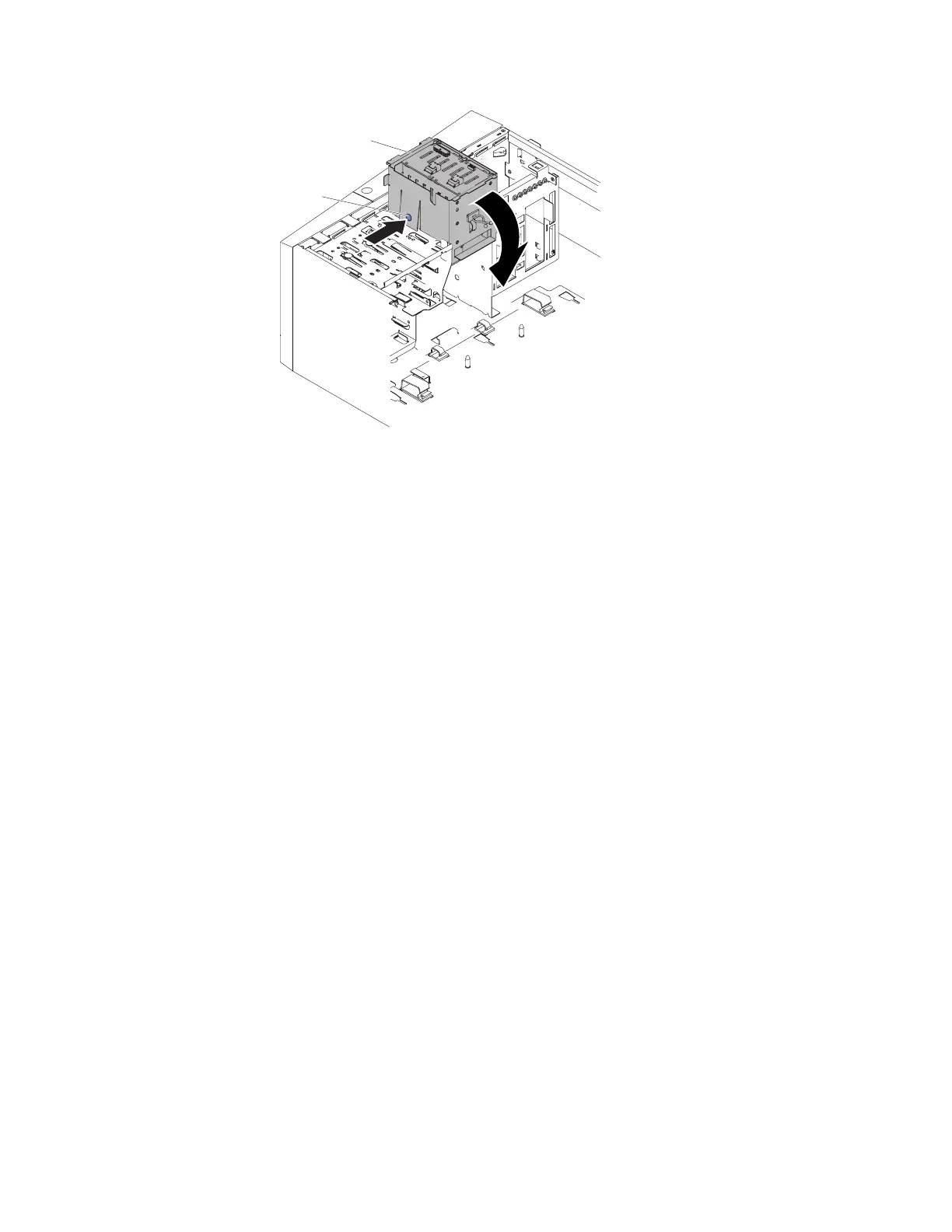
Hard disk drive cage
Release tab
Figure 158. Rotating hard disk drive cage into chassis for 5U server model with hot-swap
power supplies
246 System x3100 M5 Type 5457: Installation and Service Guide
 Loading...